If not, please excuse me, but this was the most knowledgable and supportive forum I came across… Also pardon my obvious lack of experience with electrical systems! :o Any expertise would be greatly appreciated!
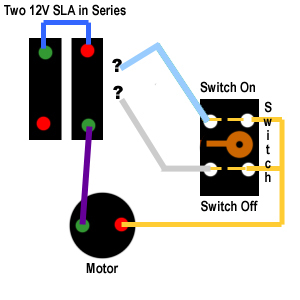
In swapping the batteries on a 24V Cordless mower, I carelessly did not record two wires’ connection points to the battery series. In fear of short circuiting the system, I am seeking advice. Switch illustrated is a ‘dead man’ set up. The ‘switch off’ position seemingly/possibly had a ‘dynamic motor braking effect’.
A diagram is attached below:
Thanks so much!!; Sincerely!,
Recovering Petroholic
Hmm thanks Lazlow… I’m voting blue to open positive too.
The diagram is not really to scale… my camera is away for a bit. The batteries are in definitely in the right configuration… I may have to pre fuse the leads before connection (test connection)… in order to prevent shorting… a bit nerveracking. Was hopeful someone may have swapped out their batteries on something similar…
This is a Lowes Taskforce 24V. I believe the same wiring set-up as Black & Decker’s cmm1000 and cmm1200. Anyone happen to run one of those?
According to this there should be no direct connection from the motor to the battery. This would make sense as the run/recharge paths could not be reversed otherwise.
Thanks for giving a hoot! Aha - that is actually a B&D Parts diagram! Similarish to my set-up. I just found a magnified copy online - ‘parts’ is just about the only search term I hadn’t googled! Appreciate that.[/SIZE]
The brush leads run different on mine. Instead of going through an electric board… the positive brush lead runs right to the switch (along with my two mystery leads - as in diagram), the negative definitely goes to the (-) of the battery!?
Edit: The system just keeps dropping the quality of the image. I can look at the copy on my desktop and it is fine. If I save the copy that is here it is junk. I just went to black & decker and followed the links.
Thanks for giving a hoot! Aha - that is actually a B&D Parts diagram! Similarish to my set-up. I just found a magnified/clear copy online - ‘parts’ is just about the only search term I hadn’t googled! Appreciate that.[/SIZE]
The brush leads run different on mine. Instead of going through an electric board… the positive brush lead runs right to the switch similar to the one at the handle as per the B&D exploded schematic) (along with my two mystery leads - as in my drawing), the negative definitely goes to the (-) of the battery!?
I took a closer look at my switch (similar to the one at the handle as per the B&D exploded schematic) and updated the drawing here (and above):
this is impossible to solve without some more info. how does this charge: where are the connections to charge it? I’m assuming when the switch is off is when you connect the charger?

 Was hopeful someone may have swapped out their batteries on something similar…
