That is fun to watch.
It also shows some interesting data.
My knee-jerk reaction is that cells 9 and 17 are weak, but I also like your theory about your spade connection being the weak link. What is interesting is that the cell V comes right back up once the load is removed. It’s not that the cells are out of balance, it looks like a resistance/measuring error.
I will sleep on this thought and probably think it is crazy tomorrow.
What are you running for cables between the batteries?
The ANT BMS is passive, it slowly brings down the voltage of high cells to match the level of low cells by burning off the voltage (heat). at about 200ma
The JK’s use active balancing and transfer voltage (@ up to 2A) from one cell to another, normally high to low cells. This is much faster, and more efficient (no heat and higher current)
Now I know. I was expecting my BMS to transfer voltage, explaining this ever so proudly and confidently to my wife when my fiasco first started. The JK ones only seem to be marginally more costly than ANT
Did you attach the balance wires to the cells or did you use an adapter in the existing battery config?
Can you map an accurate diagram as to their hookup sequence related to the ending of one pack and jump to the next?
(I’m working a theory)
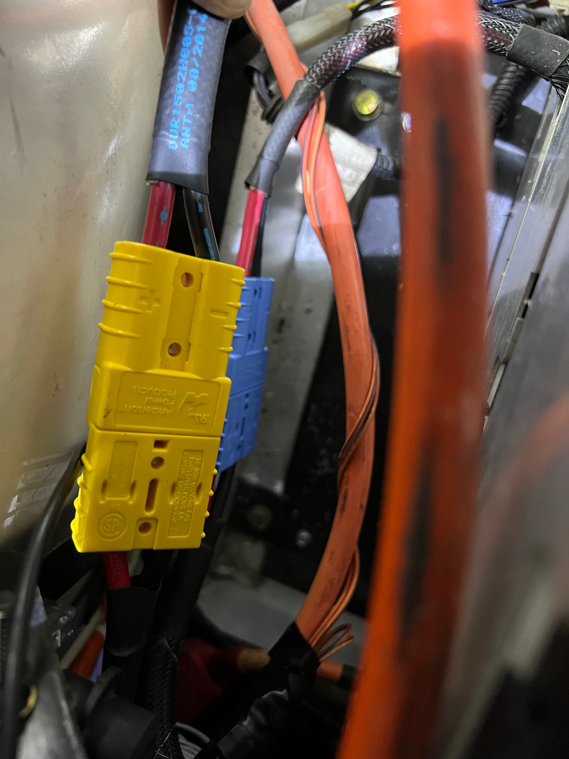
Basically I think you are getting resistive losses in your jumpers and Anderson connections. I would like to see something better than 8ga interconnect wires.
What kind of connection is on the battery itself?
I will draw up what I think is happening when I get home later today.
Here are all of the balance leads connected to the BMS. This connection splice circled in Red has been replaced with an Anderson connector since this picture was taken fwiw.
Pretty sure the problem is the spade connectors. No way they can pass 300a, voltage is dropping at the connection and BMS is seeing it as a low cell. The fact that they are the first cell after the connection is the give away. I put a good ring terminal on each wire, put a hole in the spade,PITA and then sandwiched the spade between the 2 ring terminals. No voltage drop. You might get away with soldering the connectors to the spade. INWO is the expert on that.
The BMS is able to read each cell with the balance wire, and it is referencing it to the balance wire that comes before it (with exception of cell 1 which has the black wire). It does this through the jumper that connects the two cells (drawn in blue).
When you get to cells 9 and 17 it goes through YOUR jumper connecting the batteries together. This works fine at low currents but once you really start to pull some amps there is severe voltage drop due to resistance. This is like starting off with a 1 in pipe tapering down to a straw and trying to suck through it. It works if you drink slow, but not if you are really thirsty!
The BMS is reading this voltage drop as cell difference and shutting you down.
In my opinion (whatever that is worth) The spade connections on these cells are not near good enough to support the currents needed for what we are doing. Are there specs on those?
Hans and Frans would call this a girly-man connector. We need to pump you up!
I understand the convenience of having anderson connects between these cells but each time you introduce a break in a cable it introduces more resistance. Plus- it looks like your andersons are only rated 50A? Sure it is doubled up but you need to build these to 400A specs. (last car I rode in we were climbing a hill at 300A).
I think you would do well if you use at least a 6ga (4?) interconnect wire if you can get it attached to your battery.
Third vote for pumping it up!!
Following along I guess I did not realize the spade connector was for battery to battery connections, I thought it was for BMS connection on each cell.
As @LithiumGods and @AssyRequired suggested get some good copper wire and ring connectors and both together for a good heavy duty junction.
I agree, and will most likely drum up the courage to tap it so I can bolt it down, but my devil’s advocate response is then how is BMW able to do it? I’m sure they have a proprietary board or connection that I don’t have, but surely it works for them?
This diagram’s polarity is reversed , otherwise it’s correct. Negative is on pack 3 at the top , positive is on pack 1 on the bottom.
I don’t remember for sure, I had to order them from a local electrical supply, but I want to say they are rated at least 40-50 amps as I was told that size is typically used in dryers (I know, still not 100+ that we may need)
I don’t wanna be the “but it worked just fine before” guy, but this setup did work just fine when it was in the 02. I guess the combo of a bigger motor and a different controller/dc converter may be drawing a little more than the T2? Or the spades are loose from disconnecting/connecting when swapping over?
Regardless, sounds like the bottom line is I need to go over the pack and make sure all connections are solid and re-evaluate how it’s all connected.
this setup did work just fine when it was in the 02. I guess the combo of a bigger motor and a different controller/dc converter may be drawing a little more than the T2?
Ah, but not quite the same. I went back and read about how you were not running the BMS on the old car. You were probably having the voltage drop issue but just didn’t know it. (unless I read the timeline wrong?)
then how is BMW able to do it?
I suspect that you are only running one pack of several. Depending on what car this originally came from, It could have been 1 of 8. This spreads the load out quite a bit. If all parallel then a 300a pull would only require ~37a from each pack.
What does the battery side of this connector look like? Do you have a pic of what it looks like under all that plastic? How much meat do you have that you can attach to?
LG’s solution is almost exactly what I was expecting. Using both top and bottom of that tab for contact is good. It just might be tough to get it all tucked in clean enough so you can stack them. Oh wait… On your new car you have them in under the back seat?
Watching that data log while from your last trip was very educational.
What app was that?
The max amp draw I saw was only about 85A(I think?) before it shut down. You should be doing better than that.
but I never experienced power loss when in High, or at all honestly.
Are you talking about Total Power Loss? ← the BMS is doing that now
(You probably know that - Just getting on the same page)
Or just that it never felt low on power?
Since all you have to compare it to is maybe a couple of runs on a tired old LA pack, this pack (as is) would be a great improvement. I suspect you will feel an improvement once you start pulling more than 100~200A.
Found the stock cables for mine. I had looked for them previously but gave up. Your part number helped a ton in tracking it down. Gonna order a few of these and hopefully eliminate any potential connection issues. I know I can do it cheaper with ring connectors and a bolt, but I figure if this is how BMW intended for them to interconnect, that’s probably how they should connect.