0/0 that should weight the car down a little… LOL
Ac circuit size.
14awg-12awg ?
The AC Circut is a 30 amp breaker
The charger is only 12 amps on 240vac. So 14awg or 12awg is plenty.
If you don’t use your j1772 for heavier loads, put in a 20a breaker.
Or a 20a fuse or breaker on the Gem side. Seems silly to run 10awg, but I guess you could. I would not.
Wait this charger will only charge at 12 amps?
The delta Q charges 15 Amps at 110
What’s the advantage of 220 at 12 amps as far as speed how much faster will a 220 charger charge at 12amps Vs a 110 at 15 amps
29 amps @ 86v…
Almost twice as fast.
So Dave What’s go’s Where. I’m gonna take these wires off the J1172 and extend them
To the charger at the rear of the car. Can you let me know what go’s Where?

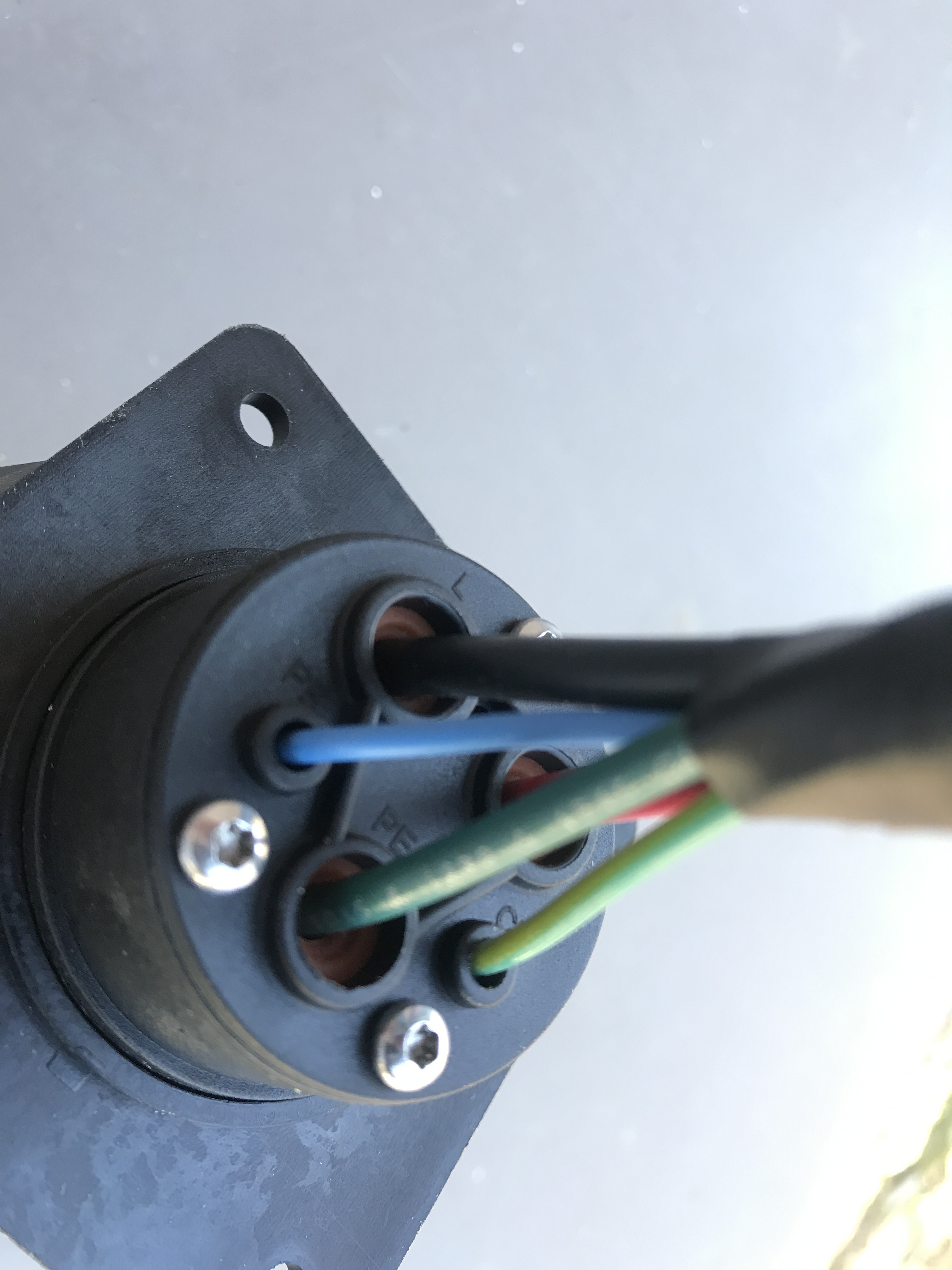

Sorry for the confusion: where do the Small blue and Green Anderson plugs go to.
Now I’m confused. Do I need to draw a picture? 
The other end plugs into the J1772 charger. Color to color.


1 Like
You should be safe with bms control. As I recall, charger will restart using the bms input.
That means charger can charge, balance, charge, balance, ad infinitum.
If worried we can easily add a hvc relay on the 12v supply.
It seem bms will always fail safe.

I know this may sound stupid but I don’t wanna give up my 110 charge ability. I have found myself far away from home and having the ability to 110 charge is real nice. I could see myself using the 220 charger 99% of the time
Can the BMS control 2 chargers?
I would most likely never use both chargers at the same time so could the BMS 24 charge controll feature work on both chargers could I piggy back the new charger onto the existing charge control
Yes, you can.
I believe the big charger uses an isolated input.
I’m somewhat worried about the grounds. Ie. The negative inputs/outputs of the 2 chargers and bms.
If all are reference to B-, should be no problem.
Get an ohm reading from the minus bms input to the B- output.
This is on the big charger.
To connect both, pick one of the bms charge control plugs. Cut the other off and wire in parallel to the one you will plug in. Or build a two into one adapter.
You didn’t find one by chance? I recall making one.
Then cut the positive control wire to each charger.
Put a diode in series with each one. Cathode to each charger.
Anodes can connect together at bms output.
In400* is fine.
Another way is a dpdt switch, switching the wires from one charger to the other.
Make sure to test bms control first so as not to introduce another unknown.


Ok well sorry for the delay. I have to laugh at my self. I have a 20 cell Bolt pack. It’s 2/ 10 cell bolt packs stacked on top of each other.
The stack on top is cells 1-10 the stack below is cells 11-20 well after installing the new charger noticed the charger was only charging at 1/2 what I thought it should.
And next thing I noticed was cells 11-20 were way lower then cells 1-10 my pay was Way Un balanced it Never came more then -/2 a volt out of balance why all of a sudden. Well it turns out I had the new High Current charger only hooked to cells 1-10. Yup that’s right The charger was Zapping the upper stack and the trickle down would charge the lower pack but not at the same rate.
Well I got it all sorted out. I drained down the high pack to the same voltage as the low pack
And then hooked up the charger the correct way and started where I should have.
30+ Amps right off the bat. Charges in what seems like No Time at all super happy.

2 Likes