I have the bottom dash off too. I didn’t do any more testing tonight but you are right. It looks like the plug for the converter was patched in. Little messy but a fairly nice job with shrink wrapped connections. I will test for 12 volts tomorrow.
What is the PSDM?
Apologies- Sometimes I forget that there are quite a few different generations of cars dropping in here. I scrolled back to your original post and see you have a 2002. I think I have a few documents that cover your year. Let me study up and get more of a grip on what you are dealing with.
I still think we are going in the right direction by checking for 12v coming out of the Converter. Also- keep an eye out for an inline fuse or a fusable link.
Took the day off yesterday to gather my thoughts. Using chart above for the plug going into the converter I started to test the wires with a ohm meter. Grounds ( terminals 4,5&6 are good, #1 to neg of 72 volt is good. #12 to pos 72 volt is good ( obviously tested with main switch off and for a little extra safety a terminal pulled from one of the batteries). Not taking any chances. Turned power back on and plugged everything in. I have 13 volts at terminals 9&10 which are for the un-switched loads. Happy to see converter is working.
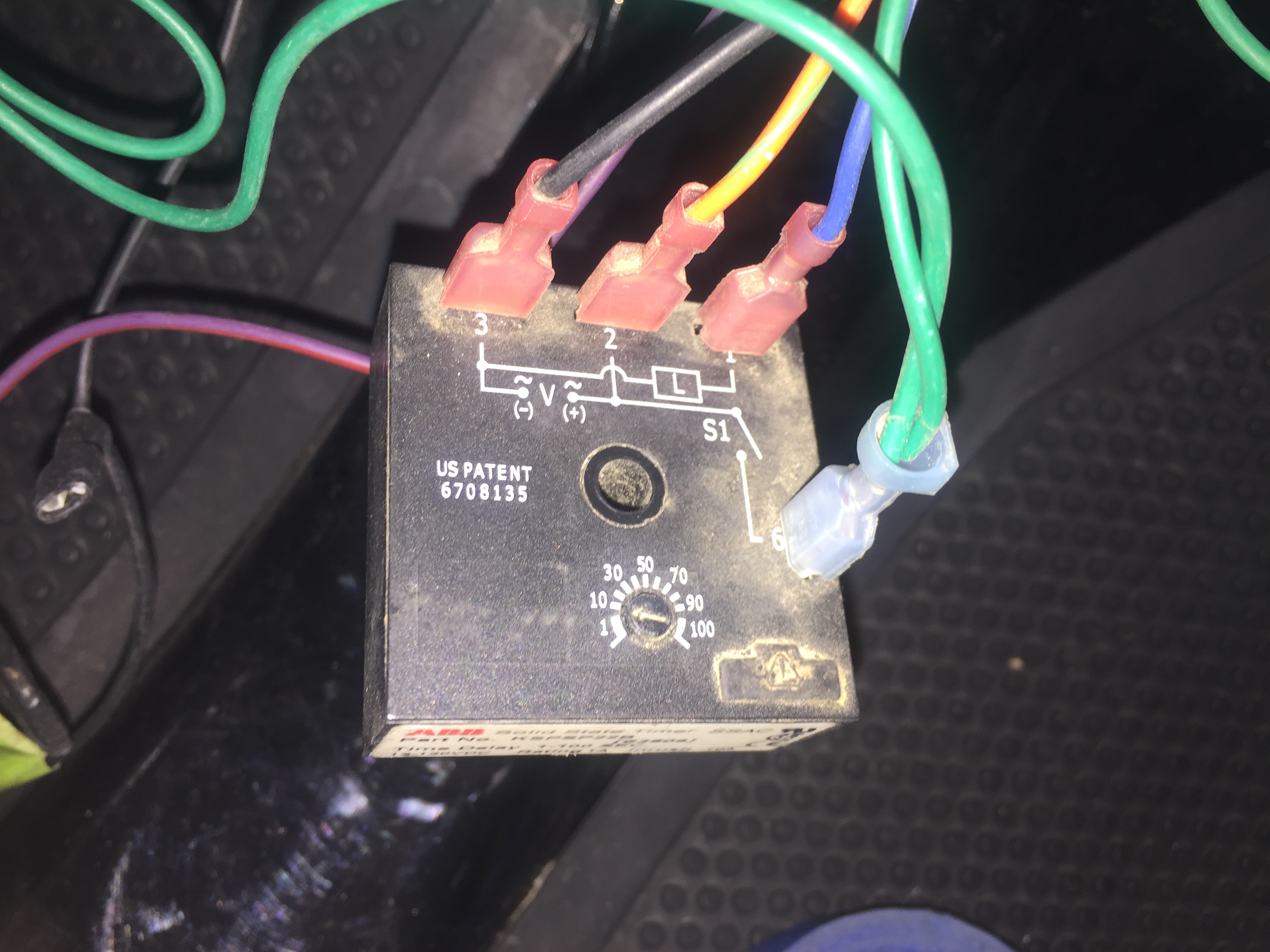
Switched loads however are dead. There is a little black box marked timer which I suspect may be the problem. I’m not sure exactly how it works so I’m not really sure how to test it or bypass it. Thoughts anyone?
Yes, but I need to look at the schematic. I believe the the always on 12v gets switched back into the converter control input to activate 12v out.
This is through the td off timer to keep 12v on after keys is turned off.
This stuff will really make your head spin. Each time I look at it I come to a different conclusion. Now I suspect the charger. I installed a RFF super charger 2 years ago which has worked flawlessly. There are 4 wires coming out of the RFF charger. 2 are for the charging which are obviously 72 volts. The other 2 are for what I believe to be a safety which prevents you from driving the vehicle away while it’s plugged in. They are small white and black wires that come out of the charger. When I installed the charger 2 years ago I connected the white wire to red/green wire which comes from the ignition switch and the black one that goes to a green wire which feeds the timer and the relay which I previously suspected. If I understand this correctly those 2 wires from the charger just open or close the circuit that delivers 12 volts to the timer and the relay. The charger still charges when plugged in.
Yes, but show as green not white above.
In any case check for 12v timer p6.
Which triggers timer P1 to converter.
Test from ground timer p3.
Timer p2 has 12v always.
Did more testing and eliminated the charger. Green wire which feeds 12 volts to the timer and the relay is activated when the ignition switch is turned on. When unplugged at the timer it has 12 volts. When plugged into the timer the voltage dropped to about 1. As soon as I unplugged the green wire from timer the relay started to work. Could hear it click each time the key was turned. During all of the testing suddenly everything started to work. I am back to suspecting the timer.
Apparently I spend too much time typing out my novels of instruction here. There were helpful posts dropped in as i was going through all this in my head. They may still help others that drop in later so, DAMMIT I’m posting this anyway!!!
Yeah, You might just start from the beginning. It wouldn’t take long to check these connections. Your description sounds like the interlock wire changes colors a couple of times along the way.
…
I believe you are correct in thinking it is just a relay dry contact that passes one wire to the other through the charger. To bypass/check the charger interlock, disconnect the charger and jump the wires and see if the car wakes up. (make sure you aren’t jumping the battery wires ← This would be bad!)
…
You could also check the charger side with your Ohm setting on your meter. 000 is not plugged in / OL would be plugged in and charging.
…
If this checks out then move to the timer. Inwo just posted some pin info to help with checking that.
If you have 12v at 2 - Jump pins 6(Grn) and 2(Org/Grn) to see if it clicks. When it clicks you should also get 12v power out on 1(Blu).
…
If still no change?
jump pins 9 or 10(Org/Grn) with 3(Blu) at the DC/DC converter and you should get 12v switched now going to the fuse panel.
…
Ok. Got it. Learned how to post a photo today. Green wire feeds 12 volts to the relay and the timer. It comes from the ignition switch but first it must pass through the charger for that safety that I previously mentioned. Tested green wire at the timer & it did not have power. As soon as I unplugged it from the timer it showed power and the relay started to work. Relay could be heard clicking as key was turned on and off. Plugged the wire back onto the timer and it again went dead. Did this several times while testing and suddenly everything started to work. Now I have a fully functional car with everything working but I still am not sure where my problem is. I suspect an intermittent timer.
Hang on, WHAT??? How is that timer supposed to work???l!!!
According to the diagram on the timer unit I’d say it looks like the blue and the green wires needs to be swapped.
Conflicting info is the diagram above that says the wires are going to the correct pins?
It is quite possible the timer has been replaced with a different unit and hookup was a bit off.
…
TEST THIS:
Meter black test lead to convenient ground. (You could use the black wire on Timer Pin 3. Maybe slide the terminal off a bit so you have acces to the tab)
Unplug Green wire from the timer again and test for 12v at this connector. With the charger unplugged from the wall there should be power going on and off with the key.
If yes - Then unplug the blue wire from the timer and put the green wire on timer Pin 1 (where the blue wire came off). With key off check for power at timer Pin 6. (Should be no) then switch key on and you should see 12v on pin6. Then switch key off and power should stay [on] for about 10 seconds (according to dial on timer) and go off.
If this is the case plug blue wire on to P6. Check for function of car via key.
…
** If your timer does not function like I described above. Put the wires on the pins as your picture shows.
Since your car is now working again then inspect all of these connections you were playing with. Give them a little tug and look for a bad crimp. Maybe give them an extra squeeze with the crimper. Maybe it was just a crusty connection and you just re-seated with all this unplugging.
Report back your findings.
Good catch, but it’s just a dumbed down marking.
What is shown as n.o. contact is actually the trigger input.
The user would wire a switch as marked between yellow and green wire.
The box with the L is load.
Yes- I kinda have my doubts. It didn’t make sense that it WAS working wired like that.
That’s why I REALLY wanted to have him go through the steps to test it before swapping wires around willy-nilly.
@PandD The important take-away from this might be that when the timer was unplugged (guessing the green wire?) the power returned and the other relay started clicking. Now, when plugged back in everything appears to be working?
I bet that double wire crimp has been wet once or twice and is not the greatest.


