I have to see if I can get the T1 programming cable setup working it seems. Thx
Well, if that happens LMK, I have a disassembled short GE 5 out in the garage, most parts are in decent shape and hold no interest nor value for me anymore. This motor is going to end up as scrap metal in a few months. I’m in NorCal, so you can get it next day with GSO.
1 Like
Looks like it is the programming as the 4 brushes look intact. Opened up the back of the motor.


From what I can see in the video, it doesn’t show enough for me to rule out any issues with the brushes. Make sure they aren’t stuck in the brush holders as well as check them to make sure they didn’t crack around the wires. Also make sure the wires are securely attached to the brushes.
I agree all looks good but tough to tell. If you have compressed air, blast out the internals real good before capping it back up.
Make sure brushes are not stuck (they look Ok).
The only other thing you could do while in this thing is run some sandpaper over the comms to clean it a bit, but it looks pretty flat as it is. It’s a minor pain to get that brush cluster off but possible. You get more length on the brush wires if you just go all in and remove the connector studs.
Do you follow what I was talking about how to get the bearing retainer plate back in place?
When you get this thing back together put your meter on the lugs and roll the car back and forth to see if there are any dead/open spots in the rotor causing the jumps.
the surging is an evenly spaced/timed thing and quite regular so I was looking for a missing/broken brush holder or wire. All wires and brushes are where they are supposed to be and all the springs are where they are supposed to be and move with the brushes. But, to be 200% sure I will stick some Popsicle sticks under the springs to unload the brushes and pull out the brushes plate and take a close look at the brushes and wires.
As for putting it back together, I don’t know how I’m going to do it without pulling the motor since gravity is pulling the center bearing ring out of position for the screws in the cap. I would feed some 14 awg wire through the holes in the cap and the threads of the bearing ring but the second I remove one that side with flop out of position so the screw won’t find the threads…
Byron mentioned some all-thread(long screw) but that would have the same effect unless the threads and all-thread were a really tight fit so I’ve not figured this out yet…
Maybe I didn’t make myself clear enough.
Get two long screws. I used like 3 in found at HDepot. I think those retaining screws are 8-32. It doesn’t have to have threads all the way out to the end.
Cut the heads off.
For clarity, now we will call them alignment pins.
Thread the long pins into the bearing retainer.
They are long enough to be the first things that go through the end cap screw holes as you are bringing the cap up for install.
Align the end cap with the bearing. Gently rock it on. It may need a bit of tapping.
Fasten end cap with the outer bolts.
Pull on the long pins to bring the retainer up to the bearing inside.
Hold one pin tight, then unthread the other pin.
Grab one of the original retainer screws and hopefully catch the retainer on the firts try.
Cuss a little bit when you realize you left the retainer screws on your workbench across the garage.
Snug up the retaining screw and unthread the other alignment pin.
Install the other retaining screw and tighten both of them.
so the hope is that the friction of holding/pulling on one of the threaded ‘alignment pins’ so it holds the bearing plate against the bearing… that friction will hold it in place so the other alignment pin can be removed and a screw installed and tightened to provide the same friction from the other side.
Makes sense when the motor is removed and the splined end is flat on the table. Not sure it will work with the motor horizontal as in still installed as mine is currently.
Will have to see if I have some copper I can thread and use for these alignment pins.
Yup- You got the idea. I built mine horizontal on the bench.
I suppose you could use a drop of blue loctite on the pin you plan on leaving in.
Possibly a tiny corner of paper in the hole when you thread in the pin just to make it tight?
Remember when putting your cables on the studs to back up the lower stud with another wrench if you have one thin enough.
Things look ok.
These should work once I cut off the nubb.

Closer look at the commutator.
I sure hope there is a little something besides windings between the rotor and armature windings…
Also, the bearing on this end of the motor needs replacing. Spins free, sounds dry and has a little side play.
I More/less agree. There are a couple of grungy spots in there that could use a clean, but otherwise I see nothing major going on.
Put it together and if you have a floor jack see if it’ll run in place.
Take another vid of that…
1 Like
I think I’ll pull the brushes board again and run some emery cloth over the commutator to deglaze it a tiny bit. I should have sprayed DeOxIT after rinsed it off with electronics parts cleaner. It’s on a floor jack now as that’s how I unloaded the right side to remove the shock.
I’ll put it back together tomorrow and try to see if there’s anything audible on the surging side when up in the air. It’s really looking like the controller programming is off for 84V lithium pack and a 5HP motor. I never touched the programming on the original T1 since after the lithium pack install it would hit 30 on the flats and close to that up the little hills we have at the beach.
If your going to be spinning the motor to clean up the commutator, I’d suggest pulling the motor and doing it on the bench. I can’t imagine it’s good to have everything inside rubbing on each other
the thought was to just rub the emery cloth on the commutator, not really spin the rotor to do commutator resurfacing. I’m going to put the end cap on and do a brush continuity test as @AssyRequired mentioned. This problem I’m seeing, the cyclic surging, is in the controller/controller programming.
Back together and a shout out to Byron for this idea of some long threaded rods to hold the back bearing retainer in place while assembling the motor. Worked GREAT!
Took it up/down the street and while I didn’t feel or hear what I was calling surging but it seems to be limiting power. Picks up speed going down hill but it’s not applying much throttle/power. Going up hill(very slight incline) it doesn’t go fast at all, 5MPH maybe and Turf/Road switch does nothing. I checked voltage and the Turf/Road switch is functional at the controller.
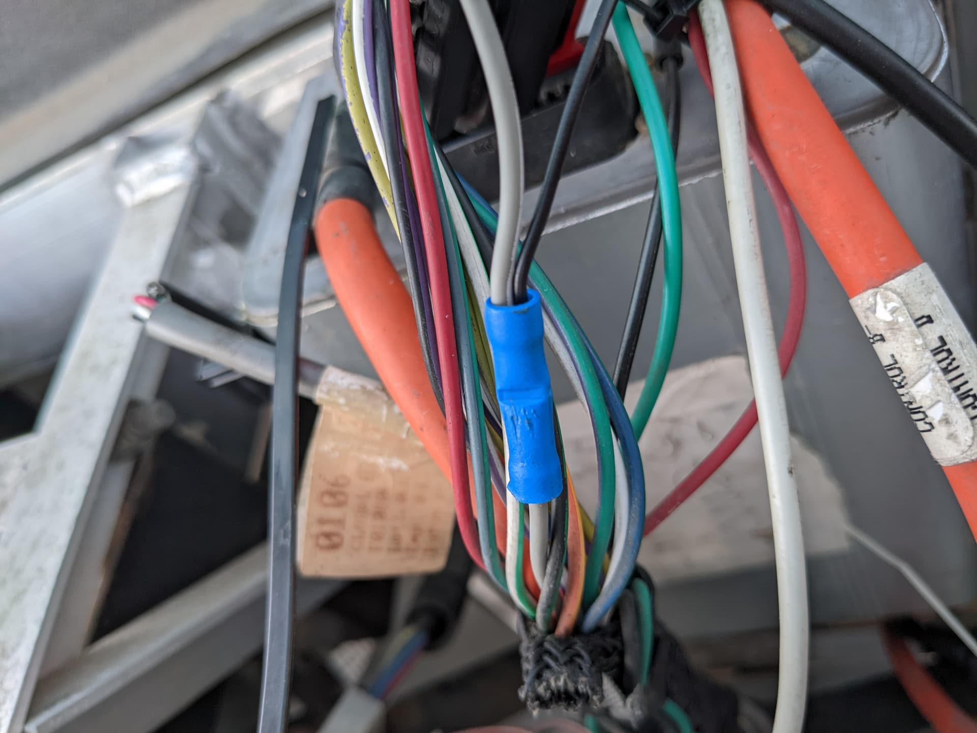
Speaking of controllers, this is a T2 and the only difference from a T1 and T2 at the connector are 2 signals, Pin 20( Negative ) and Pin 21( Motor Thermal Switch )… soooo, is this what ‘limp mode’ is like? Without Pin 21 driven High or Low is the controller limiting what it will do?
I suspect so. It totally sounds like this thing is in ovetemp/turtle mode. The other threads on this have a jump from P2 over to P21. Without a BDI (Yet) it is difficult to tell. I always thought the temp wires needed to be twisted together to bypass, but what do I know? (more research clearly needed)
If you don’t have a proper pin handy, you might get away by shoving a wire in H21 ← (hole 21) for a test and to get you going.
I think I have some pins I can send you for a more permanent repair.
If you are into pictures- here is convenient graphical description diagram: (Thanks Grant!)

Follow the path of others!
1 Like
The T2 doc you emailed me showed me that the Motor Thermal Switch was between Pin 21 and B+ and this thread validated it is normally pulled High( GE to D&D motor swap issue - #4 by Inwo ) so I’m pretty confident a jumper of some sort will get me to the next step in this process of getting the old 2002 running again.
I don’t have any crimp pins in my supply that are this big so I’m going to look for an old PC power supply to see if the input power connector fits.
Pulled a pin from an old PC Power Supply(PS) and pushed it in the back of the 23 pin connector to hit pin 21 then connected it with B+ on pin 2 but no-go. Still get the slow don’t-want-to-go feeling.
UPDATE: it worked! I had to release the red pin locking sleeve and work hard to get the square pin connector into the round socket far enough to make contact with the controller pin. I did not try Turf/Road switch but it spins the front tires like it used to.
1 Like
Fixed all pretty-like. Besides the crimp connector which is there to prevent any flexing at the solder joint, I put heat shrink over the joint/crimp connector.


2 Likes
Now we need to get the PID hooked up.
Next time down that way I’ll bring my laptop and we can see what is in there for numbers.
1 Like