Apperently Internet explorers “[x]Always open link in new tab” doesn’t work worth a #uck and just killed my message. So to make a long story short.
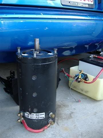
I’m picking up a '92 yamaha 1200 chassis. I plan an EV conversion on it and had a question about batteries. I’d like to calculate (roughly) the range. I have a 6.5" adc motor, controller, and 8 SLA1165 12v 55ah sealed lead acid batteries. I might be able to cram at least 6 and maybe all 8 into the chassis. They weigh 38.5lbs each and all 8 will be 308lbs. The motorcycle weight with gas and oil was originally 617lbs. I’m not sure of the ICE engine weight. I’ll weigh the chassis soon and let you know. What is the capasity of a 96v 55ah (rated) pack? I don’t know how to convert that into killowatt hours. If I can accelerate with traffic I’m happy. Around town is about 45mph average.
KWH is 55Ah times 96Volts = 5.28kWh. The pack I’m putting in mine is somewhere around 3kwh. Thats a pretty good size pack, just be careful on weight. You should be fine though. 8 might be alot for the bike, but see what you can fit in.
I don’t know how to calculate miles from kwh, because you need total weight, rolling resistance, wind resistance… But I think its kwh divided by WH/Mile. If you have 5280, and lets just say cruising you use 150wh/mile (probably lower)… it comes out to around 35 miles.
do a search for UVE’s electric vehicle calculator.
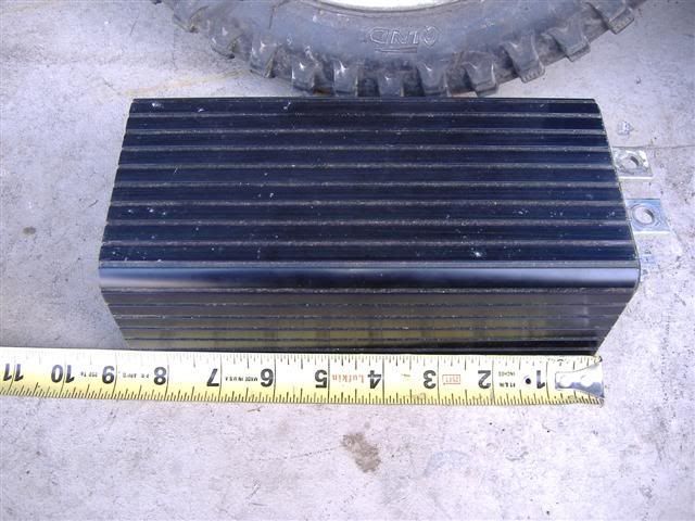
The motor is shown. Everything was in my Seadoo but that’s done now. The controller is a Curtis but I’ll be gutting it and using my own mosfets, diodes and pwm drive circuit. I’ll raise the controllers voltage to 120v. It’s just cheaper that way and it’ll do what I want it to. I’ll have adjustable current limiting and throttle ramp to help prevent those nasty EV wheelies. =)
KWH is 55Ah times 96Volts = 5.28kWh. The pack I’m putting in mine is somewhere around 3kwh. Thats a pretty good size pack, just be careful on weight. You should be fine though. 8 might be alot for the bike, but see what you can fit in.
I don’t know how to calculate miles from kwh, because you need total weight, rolling resistance, wind resistance… But I think its kwh divided by WH/Mile. If you have 5280, and lets just say cruising you use 150wh/mile (probably lower)… it comes out to around 35 miles.
do a search for UVE’s electric vehicle calculator.
What motor did you get? what controller?[/QUOTE]
I found the calculator but I can’t use it without the values for drag ect. 35miles would be great. I’d just like at least 25 out of it and I think that can be done if I tend my driving habbits.
put in a coeff lower than 0.2… motorcycles are low. Esp with fairings.
if it still had the engine you could calculate air drag and friction drag by going 60mph, and timing how long it took to get to 50, 40, 30, and then doing a curve.
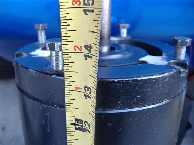
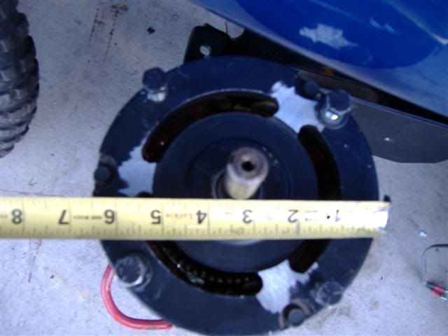
great parts though, that motor should be good, maybe a little long, but its a good 6.7" motor. VERY usable, especially if you stay 72V (even 84 and 96 is possible). My motor is 11.5 inches long, yours is just over 13… so only another 1.5". Mine fits in my chassis just fine.
What is your background in electronics? Just remember, higher power stuff, some interesting stuff happens with currents transients and ringing. Try and reuse the curtis power side. I’ve got a few 1205’s that we gutted. Mostly water dammage. you can replace with better FETs and Caps and do your own control circuit.
Its a 1231, but should give you an idea on how they do their power/control. The board layout and mounting of the FETs is nice, and brings out pins for PWM, sense, etc. It saves time in not having to design and debug your power side.
My abilities in electronics are fair. Electrical wiring is a cakewalk. I’ve built smaller speed controls for other projects bassed off 352x and 382x PWM ICs. When you speak of ringing are you talking about the battery/motor wiring or internal gate ringing on the mosfets?
I don’t think I can reuse the curtis power side. The mosfets probably can’t handle the voltage. I need the drain-source breakdown rating. IRF made them for curtis if I remember right and the number was either scraped off or some custom component. Again…manufacturers don’t like handing out info on it.
Lets blow up this motor, burn down a garage with it, and claim… “ADC withheld information that could have prevented the accident” …and sue. =)
well, I mean reuse the board, not the components it just helps to have all the runs there. The 1200 series (48V, 72V etc) have similar power boards. So if you can swap out the fets and caps and diodes for higher voltage ones, its a great start. thats what one of my buddies is doing. Just get the Fets you need in a footprint that fits in the curtis, and same with diodes.
Ringing in the FETs is the highest concern. When it rings, you can get voltage spikes higher than the FET rated voltage and it stresses it.
[QUOTE=frodus;2408]well, I mean reuse the board, not the components it just helps to have all the runs there. The 1200 series (48V, 72V etc) have similar power boards. So if you can swap out the fets and caps and diodes for higher voltage ones, its a great start. thats what one of my buddies is doing. Just get the Fets you need in a footprint that fits in the curtis, and same with diodes.
Ringing in the FETs is the highest concern. When it rings, you can get voltage spikes higher than the FET rated voltage and it stresses it.[/QUOTE]
Then those flyback schottky’s arn’t working. My issue was always gate ringing but thats cause I’m a nut trying to get 50+khz out of the osc. I did find a sweet-sweet-sweet gate driver. 9amp peak for gate drive. Overkill? haha
I’m one of those people who hates to waste anything. I thought it would be nice to make use of the handle-bar mounted kill switch.
The original kill switch grounds a wire to kill the engine but is normally open when in the run position. So how do I activate a relay with a normally open switch? Here’s a quick little circuit that does that and can drive a relay when an open condition exhists (cheap and inverting). Just about any n-channel mosfet will do. The picture is just a test circuit to give you the idea. The actual 12v main relay in the bike is powered with the key on then wired to latch when the start button is pressed. That relay allows power to various other relays for the dc-dc and main contactor power (for example). The killswitch will now deactivate EVERYTHING.
Quick explanation:
The 1k and 4.7k resistors make up a voltage divider that feeds the mosfet’s gate turning it on. The now conducting mosfet grounds the relay. When the kill switch is grounded the gate is pulled low (0v) and the mosfet turns off. The 4.7k resistor also helps protect the mosfet when not in use. The diode across the relay coil catches spikes when the coil de-energizes. All your relays, including the main contactor, sould use one.
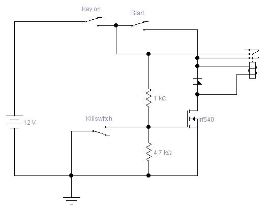
Here is the same circuit with the latch.
Quick explanation:
When the key is put into the on position, 12v is applied to one contact of the relay’s normally-open switch. The relay will not activate yet because it’s coil is wired to the other contact. When the start button is pressed the relay activates and closes keeping itself on because the relay’s switch contacts are now closed. Turning off the ignition switch will cause the relay to deactivate. Grounding the kill switch will also cause the relay to deactivate. It will not latch again until the key is on and the start button is pushed.
If you want you can connect a light to the normally closed contact to let you know it’s not “running” (latched) =) This is exactly what I did in my EV Geo. I had it light the alternator light since the dc-dc wouldn’t be on if the relay was open. Like I said. I don’t like to waste things. =)
This circuit makes a great interface to an ICE’s stop and start switches and allows them to serve the same function. I hope someone finds them useful.
EDIT - I’ve been up all night trying to figure out how to make the gas gauge work. I think I have it figured out. I’ll post that schematic shortly.
Quick explanation:
When the key is put into the on position, 12v is applied to one contact of the relay’s normally-open switch. The relay will not activate yet because it’s coil is wired to the other contact. When the start button is pressed the relay activates and closes keeping itself on because the relay’s switch contacts are now closed. Turning off the ignition switch will cause the relay to deactivate. Grounding the kill switch will also cause the relay to deactivate. It will not latch again until the start button is pushed.
This circuit makes a great interface to an ICE’s stop and start switches and allows them to serve the same function. I hope someone finds them useful.
well, the thing I wonder is, what about precharge on the controller?
I mean, you CAN slam the controller with full pack voltage, but you shouldn’t. The reason for the key on, is so you can put precharge on the controller, and then, close the contactors. It extends the life of your controller. Just a thought. And another thing, isn’t the start SW momentary?
Are you using a DC-DC converter? I was just going to enable the converter with the key, and in the LV DC side, the start switch will close the contactor. But I am using a controller that has contactor drivers built in (main and f/r), and a precharge.
Also, are you using that huge motor in the cycle? I’ve got a 6.7" 11.5" long advanced DC, the buyer backed out, so now I’ve got an extra motor again. Brand new.
[QUOTE=frodus;2427]And another thing, isn’t the start SW momentary?[/QUOTE]
Yes it is but my program I doodle in doesn’t have a momentray switch.
[QUOTE=frodus;2427]
Are you using a DC-DC converter? ?[/QUOTE]
Yes I am. It’s powered by the all-in-one control box I’m making. It’ll work in just about any diy EV. You should work with me on it and make a production version. It has all the relays and fuses in one locaton. Very simple to connect and both the 12v and traction systems are isolated including the grounds.[/QUOTE]
[QUOTE=frodus;2427]
Also, are you using that huge motor in the cycle? I’ve got a 6.7" 11.5" long advanced DC, the buyer backed out, so now I’ve got an extra motor again. Brand new.[/QUOTE]
I was going to try and cram it in there. I can’t afford single items costing hundreds of dollars. Maybe I could use yours as a spare or for a gokart project. What’s the specs? Price? Pics? Spline shaft or…?
emailed you the cutsheet… and a pic of my go-kart with a smaller motor on it.
its a 6.7" 11.5" advanced DC k91-4003, just has a longer shaft. 50ftlbs max, 18-20hp max, 56lbs, 48-96V… maybe a bit oversized for a go-kart, but perfect for a motorcycle. Its keyed shaft, and I’d like to get 500 obo for it… its brand new… and new they cost 650-800 bucks.
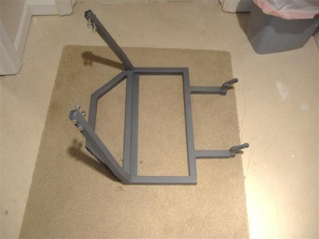
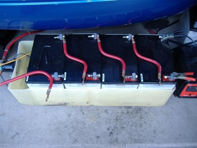
I’ve gutted the harness of ignition system wiring and beef’d up the ground. I was getting a 1v drop thru Yamaha’s wiring when the headlight was on. Since I’ll be running an HID headlamp, it’s important the ballest get full voltage or it will compensate by drawing more current to maintain 55w output. I also started the replacement engine cradle which is now a battery tray. I’m pretty sure I’ll be able to pull off 10 batteries. 55ah @ 120v? booyah!
The battery layout is:
-5 in the lower tray
-1 above the front most battery in the lower tray. Essentially where the horn is located between the front frame rails.
-4 under the tank (yup they fit)
-1 above the rear shock under the seat if I modify the shock mount. That would make #11 if I do.
The shock mount would have to be moved down about 1/2" but it’s a multi-link suspension so I just have to adjust the lenght of the links to compensate. I might do this later.
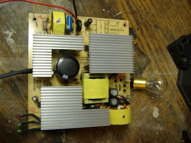
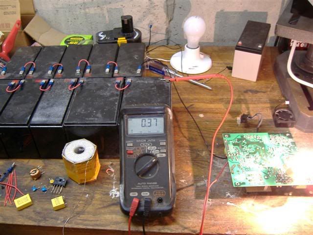
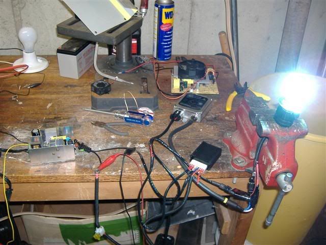
I’ve been playing with this little SMPS powersupply I have. It’s designed to fit in a PC’s CDrom bay and provide dedicated 21amps at 12v for 2 graphics cards. It’s made by Thermaltake and is called the power-express 250w. About $50 online. I stripped it of the rectifier and misc. filter caps on the primary side. They were not needed. It will power up as low as 48vdc. At 120vdc it draws 0.37 amps to power both filiments of an 1157 bulb. About 6a. So 44w input to 72 w output. I’m about to throw the HID kit on it and see how well it works.
Pardon my messy workbench. It was the only area free right now.
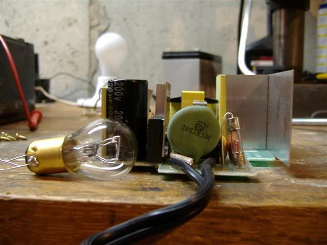
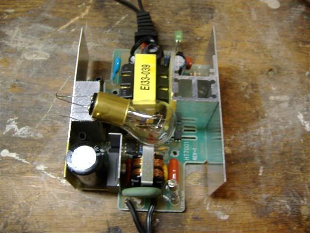
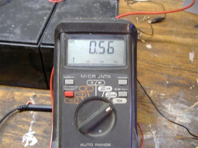
Per Frod’s request. Here’s a cheap little switching supply. It’s a Vector Travel-Mate 12v adaptor. It has a 12v lighter socket for automotive plugs. Check ebay. $10. 120vac/dc in 12v 6 amps out. Here’s a pic of the internals and the unit running off of 120vdc and powering an H4 HID headlamp. It has to put out all 6 amps to run the HID and it does this with only 0.56a off the 120v battery pack.
I ended up having to move the motor up a bit for the chain to clear the swing arm pivot. Motor is almost mounted now and uses the original ICE mounting holes. I -really- need to bring my camera along to the shop and get some more pics. =)
 it just helps to have all the runs there. The 1200 series (48V, 72V etc) have similar power boards. So if you can swap out the fets and caps and diodes for higher voltage ones, its a great start. thats what one of my buddies is doing. Just get the Fets you need in a footprint that fits in the curtis, and same with diodes.
 My issue was always gate ringing but thats cause I’m a nut trying to get 50+khz out of the osc. I did find a sweet-sweet-sweet gate driver. 9amp peak for gate drive. Overkill? haha
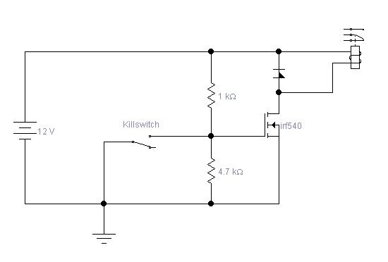

 booyah!