Hi - I will be getting my battery and charger from Dave this week and need all the help I can get!
One of the things I need to do is replace the charger. I see that it’s located underneath the controller but can’t figure out how to get to it. Really hoping I don’t have to get underneath the car.
In your case I would leave the old charger in, for now.
It will be much easier to mount and wire the new charger in the battery location.
Concentrate your efforts fitting the new battery and testing.
Move things around after everything is running smooth.
Thanks! I actually saw your previous post (thanks!) last night and already unmounted the charger! I have the dash removed and just stopped short of cutting the red & black wires cuz I wanted to see what I was going to be dealing with in the new charger and the anderson plug (it’s hilarious that you just assumed I’d know what that is btw ) .
The anderson plug is a clean way to terminate the bms, and have a disconnect plug. I send the pigtail along.
Both poles are B- making it good for 240 amps. B+ connects to battery post.
Kevin
I messaged you earlier. I have a 2005 E4 also.
Buying a battery and charger from Dave also.
Can you share the process you took to remove your charger and how you will be installing the lithium battery. I was looking at the space where the batteries are. I assume it will fit from front to back. Looks like there’s 17” between welded brackets and 24” plus to the back.
Have you figured how to mount it yet?
Hey @BigT - I saw your post pretty late and it looks like you’re in the East coast so I didn’t want to call tonight.
More importantly, though, I am just now trying to install the charger and battery for the first time and have ton of questions of my own, so I am in no position to be teaching anyone else.
I’ll share my pictures here with my questions, so hopefully we can both learn together!
I’m having a hard time figuring out how the wires from the new Delta charger need to be connected as it’s not a 1:1 match from the old Delta charger I have. Old on top and New on bottom.
The new charger has Red and Black wires that are much thicker than the ones from the old charger.
The new charger also has a multi pin plug which I’m not sure what to do with not to mention way more colored wires.
In addition, I was told that the extra wire (I think this is the voltage spoofer) needs to connect to the controller (black wire from old charger) but the black wire from the new charger is much thicker.
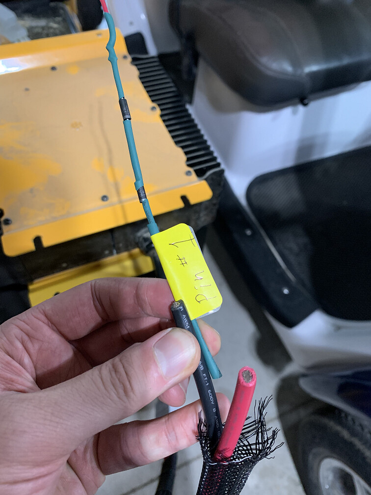
It does say Pin #1 on the label, so perhaps it needs to be connected to one of the pins in the anderson plug, but if so, which one is the #1 pin slot, and what do I do with the thick black & red wires?
Getting ahead of me on this.
Spoof goes to controller. Last thing to worry about. You have a can of worms with the battery disassembled.
Charger connection is minor, but I may need to send parts for it to mount in the original location.
I missed a couple things in the rush with George.
I can explain the charger connection, but unless the battery gets reassembled properly it may be moot.
New charger connection. Honda battery only:
The Anderson + lead connects to battery + of the old red charger wire.
2.Anderson black can connect temporarily to black old charger wire.
3.White ,old, wire not used. Goes to the sensor by battery.
Green ,old, wire connects to B+, power to Gem key. Interlock. More on this later.
For now connect both red and green to red Anderson from new charger.
Multi-pin plug. I did not send the mate, as I was out of them when George came. It will not interfere with getting car running. All it needs is a jumper from p1 to p2. I assume that you removed it.
Permanent charger power to bms:
For bms to protect battery, the black wire from new charger, via Anderson, needs to be connected to bms black marked charger. Car will charge unprotected until I can get you a long wire. Just watch it in app.
I may have mistaken, but it seemed to me like the black wire from the original charger was going to the controller. So am I essentially connecting the Anderson black to the controller?
And if the spoof is also supposed to go to the controller, then I DO need to connect the thin spoof wire to the thick Anderson black wire and connect the other end to the existing black wire going to the controller?
No, the last thing to worry about. May not even need it. Picture? Spoof is wire marked 7.5v
As soon as we are done, I’ll send the new charger plug that I found and explain how that works.
For now connect your original charger black and red to the anderson plus and minus.
Temporarily connect the green to B+ also, to bypass the interlock, until you get the new plug with green wire.
So green and red together to anderson plus.
Later the green connects to p8 of small plug. When you have the 8p plug.
Thanks, Dave.
Am I at a point where I can mount the new charger to the original location or will that cause a lot of rework (i.e. will I have to unmount the charger) later with the additional parts / BMS installation?
Also, to connect the green, black, red wires can I just twist the existing thin wires to the thicker wires from the anderson plug? I think I’d probably want to use a step-down butt connector to do it properly, but since this is temporary… But I also don’t want to start a fire!
I can send some butt connectors for that. Use electrical red or blue wire nuts for now.
Looks like you have bigger issues in that the battery may not fit.
I’m waiting to send parts until there are signs of success.
The reason why I took it apart initially is because the spoof wire was in the box with a label saying “#1 pin/15v”. The #1 pin obviously was occupied and I thought you had done that to mark the #1 pin slot where the spoof went.
I don’t do anything without having a rollback plan, so took pictures in case I did need to revert back.
And for folks that may be reading this thread, I never took the batteries apart!
Also, I’ll make the batteries fit one way or another. I was just looking to see if there was an elegant solution (extension for the plugs) before resorting to other options. I’ll use a spacer to raise the fender bracket if I need to.
I’ll hold off on mounting the charger until I have a better idea of what/how the smaller wires connect with the new things that you’ll be sending.
The jumper was pretty sloppy, but I was under the gun and couldn’t find my plugs.
It works though.
Fyi. Pin #1 Is the enable wire in lithium chargers. Previously the temperature sensor white wire. #2 Is B-. Pulling p1 low enables charger.
 ) .
) .