Hey Guys, I am personally major in EE, and my father knows alot in electronics as well like designing & creating his own HiFi amplifier and so on. And I been researching to modify a car into EV lately. But the cost is a big factor and I do not want to sacrifice the range and power of the EV so I been thinking if I can save some cost in the parts of the custom conversion parts.
There are a few parts to the EV conversion kit that are expensive, like DC motor, battery, controller, charger, DC-DC converter.
I know DC motor and batteries are definitely a must buy since I cannot make them, but for the controller, charger and DC-DC converter, they are just electronics components, so I am thinking about making them myself to save cost.
My biggest question through out the past 1-2 months of reading on EV is that, what does the controller actually do? I know it controls the DC motor, but how? does it purely control the motor’s speed and power based on varying the voltage and amp? and I read somewhere about pulses, so does it keep voltage constant but sending in pulses to control the speed of the DC motor? Please give me some insight on this. Thanks!
Gil
From what I’ve been able to deduce thus far, and if I’m wrong someone please correct me, the controller does just what you described. But there’s a bit more to it of course.
A good controller will also monitor input voltage and have safeguards for low voltage input, high heat, and motor stall conditions. The pulsing of the “output” from the controller is designed to efficiently supply the needed power to the motor while discharging as little of the supply power as possible. The pulse width modulation of the power supplied to the motor(s) accomplishes this while accomplishing the demand of the drive through detection of the “throttle” potentiometer input.
So think of the DC controller as the control system. Internally it has develops feedback to the system by monitoring input voltage and output current. The driver is part of the feedback to the system as well by varying the pot.
More advanced controllers could conceivably include the capabilities of monitoring motor temp, charge regeneration and battery health.
Thanks for the quick reply.
Seems like the controller is much more than just controlling the motor speed.
About temperature control and etc, does that requires to have an additional sensor hooked up to the DC motor inorder to work?
Do you guys think the controller is really cost effective? I mean the cost of making the Controller and the price Curtis is selling, is it worth for me to make one myself? I mean, a controller that cost over $1000 is quite alot of money.
From all the complexity and feature rich you mentioned above, I start to lean toward buying the controller and make the DC-DC converter and Charger myself.
some motor controllers are pretty fancy and have certain designs tailored to certain types of motors like DC brush, brushless, etc…
well designed controllers have PID adjustment. if you have taken any EE motor courses you know what PID means…
another is over Current/voltage limiting features, PWM output to control speed of the motor… PWM is preferred for larger voltages/currents and you want to have controller to give you that smooth acceleration; not switch directly from stop to max power to whatever your batteries can output…
yeah i think someone mention over temp cuttoff if you running too hot/long… those sensors are cheap stuff… some industrial motors have RTD inside them to prevent cooking…
umm what else?
oh there is a “open source” DC motor controller schematics somewhere on the net… don’t know if it can handle EV power tho…
i’m more interested in 3-phase AC controller design…
Do you know where is the DC motor schematics? It is good for referencing…
I will definitely take a good look into it and see what is possible to save some money.
Thanks.
I must say that it would not be difficult to make a controller, the hard part would be making a reliable, well concieved controller. Curtis and Cafe electric have been perfecting controllers for years and years. That is what they do best. It is very much an art. On the other hand, i would deffinantly recommend building your own charger dc-dc. That is actually somehting that I am going to be doing. I am going for my BA and eventualy Masters in EE, so this is my plan as well. (: The main reason I want to make my own charger is to make it the way I want. Something that I can use a computer to install charge profiles. Like for example, i want my charger to know what time it is and only charge during off peak electricy time. For my electrical service it is 9 cents /KWH on off peak and like 18 Cents /KWH on peak. I Think making your own componants is a lot of fun, and very rewarding. If you choose to go this route, keep us updated!!
I’m also an EE student, only in my second year, but motor controllers have been a keen interest of mine. Over the last few months I’ve been experimenting with PWM type DC motor controllers, and have come up with quite a bit of data. I’ve also found some high performance, but low cost components. I’d be happy to share any information I have.
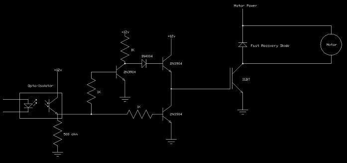
Here’s a schematic of a motor controller I designed for a project I’m doing. It’s based on an IGBT; (Insulated Gate Bipolar Transistor) kind of a hybrid between a MOSFET and a BJT. It works very satisfactorily. Most of the circuitry is for driving the gate. The gate of an IGBT holds less charge than that of a MOSFET, but still has a pretty hefty charge. The totem pole drive is capable of 240 mA, giving me a 5 microsecond transition time in either direction. The motor controller performs very well running a 10 amp motor at 48 volts, with a 20kHz PWM signal! It’s nice not hearing that whine from the PWM.
I am also concerning about humidity, and temperature.
I live in NY and in the summer it can get to 100F while winter time it can go down to 10F or below… as well for humid time too.
So I am wondering if I do create the electronic component myself, do I have to make them air tight?
Are the current controller, DC-DC, charger, etc component on the market right now all taken those factor into account? (I worry the humidity the most since it will destroy the circuit board and connections eventually)
I work with a 4H club that builds underwater ROVs (Remotely Operated Vehicles). Of course, humidity is a problem for us too. What we do for the circuit boards is “pot” them in. We build a container for the circuitry and mount the board inside. Then we fill it with silicone rubber, leaving just the heat sinks exposed. Once dry it’s sealed forever.
I really don’t know if the commercial controllers are sealed or not, they might just rely on the fact that the controller components will be warmer than the air, and therefore won’t collect moisture… Moisture is a big deal for me too, I live in western Washington State. (Seattle area)
As for temperature, I’ve been thinking along the lines of liquid cooling: Bolt the IGBT cooling tabs to a block of aluminum with water passages drilled in it. Then run rubber tubes to a pump, reservoir, and an automotive heater core (used as a radiator).
[QUOTE=gilee;2010]Hey Guys, I am personally major in EE, and my father knows alot in electronics as well like designing & creating his own HiFi amplifier and so on. And I been researching to modify a car into EV lately. But the cost is a big factor and I do not want to sacrifice the range and power of the EV so I been thinking if I can save some cost in the parts of the custom conversion parts.[/QUOTE]
I would suggest that you create an “open source” controller design. I have been wanting to do this but I am not an EE, just a hacker.
You could even have boards printed up and sold on the website, along with perhaps a parts bag, let the DIYer like us that can solder and assemble. Don’t get greedy, you’ll sell more volume. But if you put the schematics, and optionally sell the board layout for $15 download you’ll make a decent penny for your time. Should be specifically under a open source type of license of course patent it but license it for free.
This stuff aint rocket science… These controllers are overly complicated IMHO. simple still works good
Making a PWM dc motor controller wouldnt be that hard. Getting all the options like regen braking and such would complicate things a bit. But working in a PLC might make things easier.
How would using a PLC help at all? PLC’s are meant for fairly low speed industrial automation…I don’t think they’d be the best solution…did you mean to say microcontroller?
(sorry, I’m an Electrical Engineer… and have experience with both)
[QUOTE=frodus;3060]How would using a PLC help at all? PLC’s are meant for fairly low speed industrial automation…I don’t think they’d be the best solution…did you mean to say microcontroller?
(sorry, I’m an Electrical Engineer… and have experience with both)[/QUOTE]
I ment to use a PLC for all the extra stuff that can complicate things regen braking, temp monitoring, interlocks, etc.
[QUOTE=Seafarer12;3070]What is a PIC? You can get a PLC for 100 bucks.[/QUOTE]
You can get a PIC for anything between $1.75 and $10.00.
PIC stands for Peripheral Interface Controller. It’s basically a microcomputer, USART, PWM generator, A/D converter, Timer, and many other devices all built into one chip. Some of then also have USB ports, allowing you to interface them with a full-scale computer. Running at up to 48MHz they have no trouble keeping pace, and they’re Mil-spec too, so reliability is a non-issue.
[QUOTE=Sir Joab;3071]You can get a PIC for anything between $1.75 and $10.00.
PIC stands for Peripheral Interface Controller. It’s basically a microcomputer, USART, PWM generator, A/D converter, Timer, and many other devices all built into one chip. Some of then also have USB ports, allowing you to interface them with a full-scale computer. Running at up to 48MHz they have no trouble keeping pace, and they’re Mil-spec too, so reliability is a non-issue.
Definitely one of my favorite chips.[/QUOTE]
Interesting. I assume you have to be able to write code and all that to program them? What about I/O points? I have basic digital experience. I have messed with op amps, 555’s and such but haven’t messed with the more complicated chips. All of my experience is in industrial electrical and control. I don’t ever mess with any of the real small stuff.
[QUOTE=Seafarer12;3073]Interesting. I assume you have to be able to write code and all that to program them? What about I/O points? I have basic digital experience. I have messed with op amps, 555’s and such but haven’t messed with the more complicated chips. All of my experience is in industrial electrical and control. I don’t ever mess with any of the real small stuff.[/QUOTE]
Yeah, you do have to be able to write code for them, but if you do the performance is hard to beat. You can get some nice programmers and compilers for the PICs from Micro Engineering Labs inc. (http://www.melabs.com) Some of the stuff is kind of pricey, but compared to the price of a PLC the cost is quickly offset by quantity.
There are various sizes of PICs ranging from 8 to 84 pins. Most of the pins are I/Os, so there’s no lack of data that can be transferred in an out.
Most of the PICs can be purchased in a DIP package (0.1 in. pin spacing, just like the 555) so they’re not difficult to solder up, and can plug right into a breadboard for experimenting.
That looks like an interesting site. I noticed they had some books on PIC’s for the beginner. I might have to get one. The wife is a programmer so I imagine she could help me a little. I imagine they use pretty basic programming. I am just use to using ladder logic or function blocks.
There was a link earlier in the post about a homemade PWM a guy bult for his S10. I wrote him to try to pick his brain. He wrote back and talked about how great it worked but when I tried to get more information out of him he pulled that engineer superiority complex you are not capable of grasping such things. I felt like telling him I work on drives that are bigger than anything he has ever thought of. The biggest drive I have worked on is a 13.8kv drive. It is used to motor a 150 MW generator on a frame 7 GE gas turbine to start the unit. If I can understand that, I think I can figure out a small DC motor controller.