I don’t think a PLC would fit your needs for driving a PWM signal to the FET’s or IGBT’s (whichever you want to use). I seem to remember the duty cycle on the outputs is fairly slow on PLC’s.
I was looking at that sparkfun. They had some good basic tutorials. I am going to have to spend some time reading over them. The programming dosen’t look that complicated. It looks like scripting I have done in wonderware hmi.
I am still going to use a PLC to automate my house one of these days.
[QUOTE=Seafarer12;3092] He wrote back and talked about how great it worked but when I tried to get more information out of him he pulled that engineer superiority complex you are not capable of grasping such things. I felt like telling him I work on drives that are bigger than anything he has ever thought of. The biggest drive I have worked on is a 13.8kv drive. It is used to motor a 150 MW generator on a frame 7 GE gas turbine to start the unit. If I can understand that, I think I can figure out a small DC motor controller.[/QUOTE]
Don’t you hate that? I get it too, and I’m studying for a EE!
The cool thing about DC motor controllers is that they’re scalable; once you have it working on 1 amp it will work on 1000 amps, providing you scale up the components and cooling by the same factor.
If you want I can put together a “tutorial” for DC motor controllers so you could start playing around with the concept.
Thanks, I took a drives course when I was in school but there was very little on DC drives. It was mainly on soft starters and VFD’s. The electrical courses I took were geard towards industrial electrical and since DC isn’t used a whole lot anymore since VFD’s have been perfected they wern’t covered much. I understand all of the PWM since thats what is used in VFD’s you just need a whole lot less stuff for a DC motor. Most of the motors in my plant are constant speed and only emergency oil pumps are DC. None of them have a drive on them. They do have an interesting softstarter type configuration in their breaker enclosure. It is more of a step starter. It uses resistors and timers to limit starting amps.
The main things I need to get familiar are MOSFETS(As in sizing them). I have seen how they are rated and they dont make much sence to me. They have a volt, amp and watt rating but they don’t come anywere close to adding up. I would assume you would have to go by the watt rating then use your voltage to calculate your amps.
The other things I need to get familiar with are the protection circuits such as amp limiting, minimum voltage, temp, as well as fail safes. I think I will be able to figure out the microcontrollers. I will just have to combine all the stuff I do know and learn some new things. What I would also like to figure out is regenerative braking. I know how it works and but regulating it and making it reliable is what I am not sure about. Then making all in a small package. I work in a powerplant and I tend to oversize most everything and everything I am use to working with is big. So making something small will be new.
Voltage
This is the maximum voltage that can be applied across the Drain and Source pins. When this voltage is exceeded the MOSFET will blow apart at the junction. Some MOSFETs have a small TVS inside to help protect the component. I recommend this type.
Amperage
This is the maximum amperage the MOSFET can carry. Just like over voltage, if exceeded the MOSFET will blow apart at the junction.
Wattage
This is the odd one: it isn’t the maximum wattage the component can carry, it’s the maximum number of watts the component can [I]dissipate[/I]. You can find this out by taking the voltage drop across the MOSFET (caused by internal resistance, [I]very[/I] small) and multiply it by the current going through. There’s the wattage you need to dissipate. As long you’re just switching the MOSFET to full-on or full-off, and you have a good heat sink, this parameter shouldn’t be a concern.
A couple of hings to remember about a MOSFET motor controller:
The more time spent transitioning between on and off, the more heat you will have. The Gate of a MOSFET is a small capacitor, so it actually can take a lot of current to get a fast enough transition. My latest motor controller switches the Gate in about 250 nanoseconds (which is excellent), but this means my peak current at the gate is a couple of amps.
You must have a fast-[I]recovery[/I] diode [effectively] across the terminals of the motor. If you don’t have one the transient voltage from the motor every time the MOSFET switches off will kill your MOSFET. (If it has a built-in TVS, it will over heat and melt down.) This diode should be capable of carrying [I]at least[/I] 1/4 of the total current draw of the motor.
Okay that make more sence. I was looking at some pretty stout mosfets like hundreds of volts and amps but like 2kw.
So if it takes a couple of amps to trigger your mosfets what are you using to trigger them. I am not sure how much a PIC can handle but I imagine it is in the low mA range?
Is the diode for the inductive kick of the motor when you colapse the field? I have seen some metion of using the Schottky diodes. If I remember correctly they are just fast diodes.
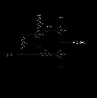
Yes, the PICs only have a drive current of 5 mA per pin, so I use a simple transistor totem pole.
This circuit works quite well.
The diode is to absorb the inductive kick of the motor, but it also allows the current to “freewheel” through the motor while the MOSFET is off, making for smoother running and less noise.
You have to be careful about those diodes though; Schottky diodes are not always fast recovery, but if you get a fast recovery diode it will probably be Schottky. I chased that one in circles for a long time before I got the difference there. The problem with standard recovery is that when the MOSFET switches back on and the diode is conducting, it won’t turn off fast enough and creates a short circuit path for just a moment. Of course, when this is happening at 10,000 times a second bad stuff happens!
DC motor controlers do not have to be complicated, my first non mechanical controller built back in the 70s to control the aircraft starter/generator I used for a drive motor was an op-amp to create the variable pulse width, driving darlington transistors to drive the pulse transformers needed to drive the high current SCRs for the motor control. Whew, that was long! If I were to design one now, I’d start with a PWM chip like but not necessarily limited to, an SG3525, into a couple of driver chips through an easily home fabricated pulse transformer to the gated of some high current IGBTs. There are several varities of these chips used in switching supplies, as a matter of fact the topology from your PC computer supply can be easily adapted to a homebrew EV speed controller. The regenerative braking can be as simple as a microwsitch on the accelerator linkage to trip a relay to switch in a high current charging diode during slowdown, that’s how I did it on my 70’s vintage EV. You can easily derive the switching signal electronically from the pot signal to the PWM driver. You can find a bunch of PWM driver info on the web, but for some innovative and relativly simple drivers look up some of the SSTC solid state tesla coil drivers.
Interesting information. I like the simpler is better ideas. I just need to research regen braking. I know how it works I would just would want to figure out some protection for the motor and batteries. I wouldnt want to hurt the two most expensive parts. I guess I need to look at the drives that are out there and figure out what options I like and work back. I am still early in the researching stages. I am thinking about converting my neon when the engine dies. It still has plenty of life. Maybe batteries will be better when the time comes.
 The problem with standard recovery is that when the MOSFET switches back on and the diode is conducting, it won’t turn off fast enough and creates a short circuit path for just a moment. Of course, when this is happening at 10,000 times a second bad stuff happens!