Just mod yours. Take the split loom off under the hood. Cover wires using aluminum or copper tape with a small gauge drain wire under the foil. Leave enough wire to connect to controller b-. Put the tubing back on.
Maybe even make sure the throttle wires are near power wires, prompting failures. Then do the shield.
Max lost his contactor by tripping it too much, the way I understand it.
1 Like
Hello all. I just had a very productive session with a Sevcon programmer out of France. One issue with the DCF we’re using is even though contactor voltage is set to 48v and holding voltage is set to 29v @ 1s, both are disabled in other areas of DVT so basically, with the DCF I had, I was sending constant voltage (either 48 or 72, I’m not sure) to the contactor coil. We fixed that by “enabling” two parameters which then enabled the 48v initial contactor voltage and the step down to 29v - it was in the “tree.”
We made some minor tweaks but overall, the message I got is that the DCF we’re working with is pretty sound which was good to hear.
One interesting thing we found was that from a dead stop, if you go pedal to the floor, with my 80v 22s system, we are seeing a current spike of a little over 400 amps. This is probably why the max current is set to 420. If we drop it to 350 which is what the Sevcon is rated for, it will jerk like crazy. For what we’re doing, I don’t think it’s a big deal, but it’s certainly worth noting that if you change max output to 350, it will not like a full throttle from stop situation.
On the throttle trip situation, I put 8 ferrites and braid/shielding on the throttle wires all the way from the controller to the firewall - I’ve been busy installing a battery box, stereo system, and chasing that contactor issue so I haven’t been using the car much, but I’ll use it a lot in the next week or so and if we get no trips, it’s safe to say we’ve found the issue.
Dave, on the already made harnesses, no reason you can’t pull the split loom off of the part in the engine compartment and add shielding, but frankly, you might be able to add some ferrites to filter out noise.
3 Likes
Thanks for the work. On the controller, I always set contactor voltages in “tree” without issues. I wonder if we are on the same page there.
Let’s hope it is throttle, and your fix is good.
I like to keep max current at max possible, and copied that from the Gem oem.
We can throttle back acceleration and torque maps to get drivability we want.
That is something to ask your guy, as I’m not sure exactly how it works.
Some dld files use actual torque maps to set torque versus rpm.
Our dld has slip maps and graphs slip versus rpm. Not sure if it works similar.
I believe this also allows our overspeed by dropping off torque at high rpms. Necessary to keep in the motor hp limits.
1 Like
Missed that.
The two contactor voltages in tree? Something else? Was not aware that the pwm voltage could be disabled.
Not the written in voltages, there’s a coil voltage output enable and a coil voltage stepdown enable (might not be the right terminology, but you get the idea), both were disabled. I will take screenshots and show you where to change them. What I understand is that the voltages written in are not output unless these two fields are turned on if that makes sense
2 Likes
Yes, make perfect sense. I had no idea that I was messing up 48v coils.
That would explain why Grant burned his up using my dcf. @grantwest sorry!
Also why they seem to run hot when should be at 29v.
1 Like
I’m pretty sure the DVT File that I saved have the contractor voltage at the higher voltages.
I don’t think the stock contractor likes 72v running threw it. Yes it gets hot
Interesting, I didn’t blow my Contactor yet but I would like to check this. Can you post an screenshot ?
@djgabriel2004 - Just for fun and so you can sleep at night, can you clip your DVM onto your contactor coil and see what is being fed to it?
Okay, in DVT, go to tree, vehicle master applications, battery application (protection and contactor), contactor voltages and verify your screen looks like mine:

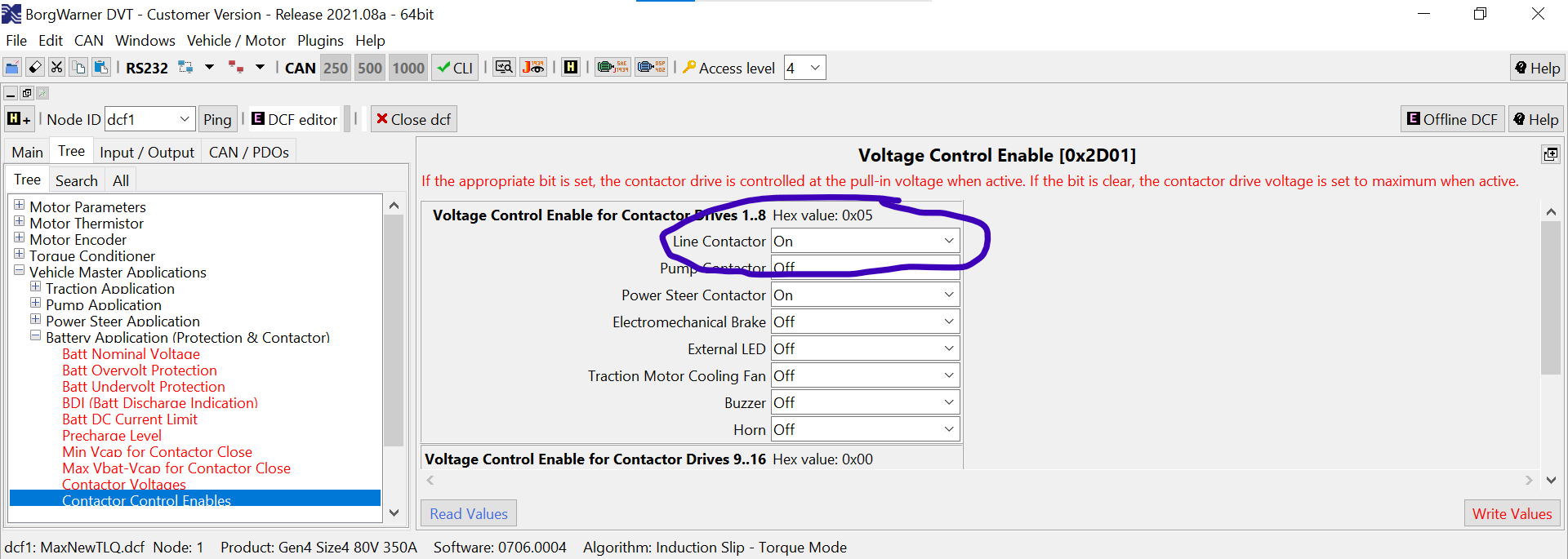
Then, go to tree, vehicle master applications, battery application (protection and contactor), Contactor Control Enables, and turn on Line Contactor:
Then, go to tree, vehicle master applications, battery application (protection and contactor), contactor hold enables, and turn on line contactor:

Now your contactor settings are correct.
2 Likes
Thanks for posting the settings!
Interesting data from my hill run to pick up the kids
Before the run

The run

After

If I’m doing the math right. used 79.5 - 76.9 = 2.6v. went 9.2 miles in hills. 9.2/2.6 = 3.54 miles per volt.
80v-60v = 20v capacity * 3.54 = 70 mile range pack with hills?
1 Like
Don’t count on volts being a linear representation of capacity. It may be close enough, don’t know.
Better to monitor ah or kWh per mile and use the know battery capacity.
You should have that data on bms.
Could also check like mpg. Make a run after charging and see what it takes to fill the tank when you get home. Small losses in healthy lithium batteries.
2 Likes
should have mentioned too… no faults on this run. I’m going to try the shielding but probably not until next weekend. Think @MaxAtMaxMarine may have nailed this one.
2 Likes
i just checked my File, This was OFF
and this was ON
I went searching for the top end again on my trip to the grocery store. I’m finding that I’m erroring out around 38 mph. Throttle position doesn’t seem to matter e.g. if I punch it anywhere below 38 no problem. If I ease into 38+ at 90% throttle, error.
I don’t really need to be going faster than 38 so it’s fine for now. I’ll try to insulate the throttle wiring and see where that lands me.
I leave that off on mine as I thought it allowed faults to open contactor. Something I do not want.
As your car runs and activates contactor, it can be a contactor enable. I believe it to be a “control” enable.
The hold enable I don’t know. Never disabled it to see if it went full voltage hold. I have my doubts of about a need for that function. But who knows. Like everything Sevcon it needs testing.
1 Like
Dave is the one that put the throttle bug in my head and it makes perfect sense. Seemingly random errors are being created because each of us has routed motor wires and throttle wires slightly differently. Proof is in the pudding - so far, no errors for me but we will see soon as I plan on putting some time on her this weekend.
As for contactor stuff, the coil leads are very easily accessible and it would be easy to hit it with a multimeter to see what those settings in DVT do to coil voltages. I’m happy to do that testing.
Thank you. It takes me about 15 minutes to set one up and do the testing. But there are 1,000 other things waiting for the same 15 minutes.
Plus it takes my old brain 2 hours to get on line with new things. ![]()
A few thoughts.
The two pins to the coil are pwm outputs, and may not read correctly with all dc meters.
One pin is just B+, however it is best to use it for internal coil suppression. We have used one pin alone and it does work.
Output is mapped in the last setting on io map screen.
Two other outputs are available. We have not verified a different output can be used in the event of an internal driver failure.
One is often used as an led driver for remote indicator.
Would there be a top end / rpm config difference between the 5kw and 8kw motors? The controller I’m currently running was repurposed out of my 2000 which we had a 5kw motor in.
I need to diff the 2 controller files. One for my neighbors from Dave and the modified one from Mike (current config and controller)