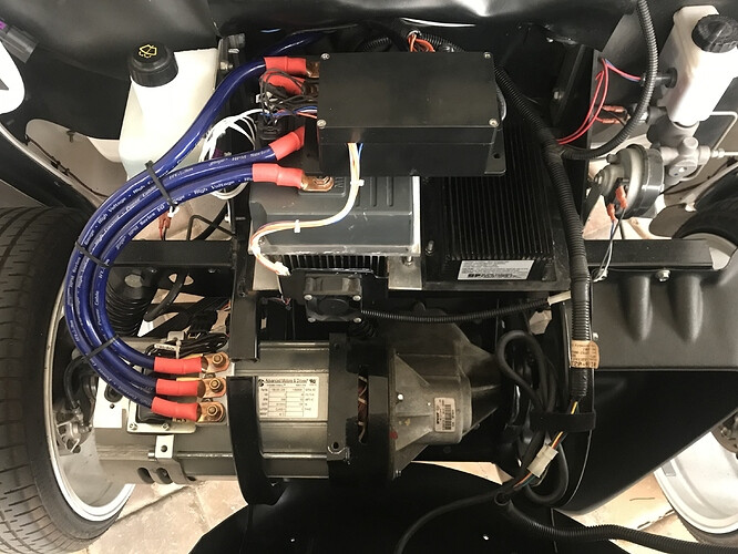
I’m working on the AC conversion in my 2007 e6 and have the motor mounted (cut ram horn) and the Sevcon installed. I added 24in 2 gauge cables to handle the runs to B+/- and 18in cables for the 3 motor connections with 5/16 studs on each as the sizing was different between my T4 and Sevcon controllers.
I’m now debating on where/how to install the PCB. I’ve got the black box MikeKC linked off Amazon and plan to Dremel out parts of it to run the cables but I’m back and forth on where best to mount it. I’ve also got to solve for the passenger side front shock as I’m not certain it will fit with the AC motor in place - I am taking the opportunity to go ahead and replace with the NEV Accessories shock replacements as my bushings were shot and shocks were questionable at best.
Anyone mounted the PCB it in a way they’re happy with and like? Pictures are helpful here. Also interested in any guidance on handling the shock. Thanks!
99% of most stock shocks will fit back in after the motor is mounted. Sometimes a little pressure with a pry bar gets you the clearance you need.
If not, you can mount the shock on the back side of the factory mount, get a longer bolt and put washers or a spacer where the shock normally goes so you do not crush the mount. It works great and has no affect on the ride.
As for the PCB board, most people like to place it under the dash and just run a wire out to the negative post of the controller. Placed in that box you can then mount it anywhere under the dash that the wiring harness will allow. It will be out of sight and out of the elements.
If the car has a DC/DC converter in the charger then there might be a blank space next to the controller - that is an ideal location for the box, but most cars do not have this open space.