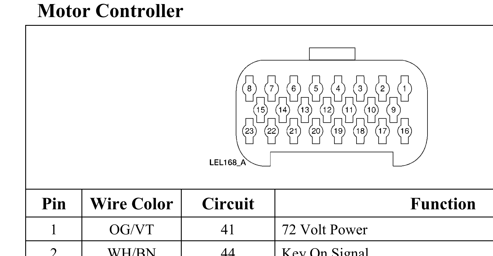
Does fuse 3 run to pin 1 of the controller and gauge cluster?
If so can the diodes for a LifePo4 voltage Spoof be installed in series with fuse 3?
Does fuse 3 run to pin 1 of the controller and gauge cluster?
If so can the diodes for a LifePo4 voltage Spoof be installed in series with fuse 3?
Why would you not just install the spoof on pin1 of the controller?
That is a good question.
Seems like it would be easier to tap off a fuse with 1 wire than it would be to cut the OG/VT wire which is a part of a group of wrapped wires close to the controller.
Though I haven’t been able to find any installation pictures or explanations on how others have installed the diodes.
Pic of the controller under the rear of the car.
Pics of fuses under front seats
There may not be much information to post as I only know of two other people that have ever installed a spoof on a Think…
I just don’t know what affects the voltage drop my have on other things on that fuse. Maybe nothing - just don’t know.
I do not recommend it. Check the current and do the math.
12v 5watt device?
About 25ma dissipation limit. Figuring 50% of the 5watt max.
15v even less.
Hi @Inwo,
I’m sorry I don’t follow.
Are you not recommending using the diodes or not recommending connecting the diodes after Fuse 3 which appears to go to Pin 1 of the Instrument Cluster Gauge and Pin 1 of the motor controller?
Edit: It appears this wire also goes to Pin 7 of the Instrument Cluster Guage “Contactor Power (Coil)”
Because the fuse circuit will in most likelyhood supply more current than your spoof can handle.
Its difficult to find more than 5watt rating. Not impossible.
You can build a higher current device if you think it worth the effort.
I did for my 2008 Tomberlin, as the controller was in a tight spot.
You could also use a dc-dc converter to be more efficient. But then the over/under sensing would be completly bypassed during startup.
Or possibly use a momentary contact switch for start-up to keep from overheating. Works with a Gem. Not sure if it will on a think.
Your Think seems somewhat different as it turns on dash with high voltage. The ones that i worked on would not work.
Do what you find works. I did not recommend 96v for your conversion to start. ![]()
There ya go. An amp or two load. Good for keeping coil from burning up at 96v, but bad for spoof. Will overheat very quickly.
Ps.
What contactor are you using? Coil voltage?
O okay I see what you mean. I haven’t tested how much current is drawn on that circuit. I’ll try to do that later today.
To clarify are you saying the diodes won’t work at all or will work though you think it would be best to install right at pin 1 of the controller?
So funny thing is this is only a 76.8V volt LiFePo4 conversion or really 87.6V fully charged.
My controller doesn’t like anything above 81.5V at pin 1. Fully charged car won’t run, drain it down to 81.6V car doesn’t run.
81.5V everything works fine.
Edit: It’s the stock contactor.
Sorry, I was confused on battery type.
Contactor will be ok.
Spoof at p1 will work.
Use minimum value device possible.
6.8v is common value.
@Inwo
Thank you for your help Spoof at P1 at controller it is.
Any recommendations on installation?
My thought is to just splice it in a couple inches back from the controller plug.
I haven’t been able to track down a picture of one installed Think, Gem, etc to see what others have done.
Do you recommend adding a by-pass switch for the spoof?
It sounds like you have installed a spoof or 3 before on a Think.
Any tips and/or pictures you could share would be greatly appreciated.
I’m thinking of peeling back the wrapping a few inches from the wire harness near the controller.
Cutting the wire going to pin 1 a couple of inches back then installing the spoof inline.
Right now I just have a series of diodes soldered together. I might connect a couple of leads to the end and cover it in shrink-tubing. I also thought about bending it into a small spiral though not sure if they’ll get hot and if they do that would be bad for heat dissipation.
.
Either way, I’d want to secure it somewhere and I don’t think zip-tying it to the wire harness would be a good idea. Guessing I can something near by to zip tie it to.

I am not David, but…
This is what I normally do on the GEM cars - wire in a quick connects on the factory wire (male and female so you can’t install the spoof backward ![]() )
)
There is very little current in this wire so making a loose spiral should be fine, very little heat. IMO.
Thanks for the reply!
The connectors on the factory wiring is a great idea. This would also make it easy to remove the spoof and reconnect the factory wire.
BINGO ![]()
Words to fill the post
Yes- Peel the tape back and give yourself plenty of room to work.
I’m curious. Did you locate and/or check to see if you had a dedicated DC Converter for your cluster. I’m pretty sure installing the Spoof on the controller will not fix the problem of your display not lighting up when Pack is above 85v.
Hi @AssyRequired,
Sorry forgot to follow up. Yes I checked and NO dedicated DC converter.
I looked back in my paperwork and found that the cluster came from autoecu.com in 2016.
Sounds like you’re saying it’s both the cluster and the controller which have safety shutoff when the voltage is too high. ![]()
Do you think a second spoof at pin 1 of the cluster would fix that issue?
…and I’d be happy if it would come on close to 85V. Right now it won’t come on at 81.51V
It has to be 81.5V or below. Even if I’m reading below 81.5V under load, radio/light/etc, if I flip off the master switch and flip it back on if the unloaded voltage is 81.51V or higher the screen doesn’t flash, and when I turn the key nothing happens. It has to be 81.5V or lower when I flip the master switch for the car to work.
@mitsured You are back to the previous discussion, finding a spoof that can handle the amperage that the cluster will pull. A second spoof might work if you can find/build one for higher amperage.
Might be able to test the theory with a standard diode, but I don’t think it would last long.
That was probably my fault. I’m bothered by the lack of pod activity at high V.
I don’t think it should be ignored.