Yep, our T2 does the same thing at 96+ volts - we set each cell to 4v and everything is perfect.
1 Like
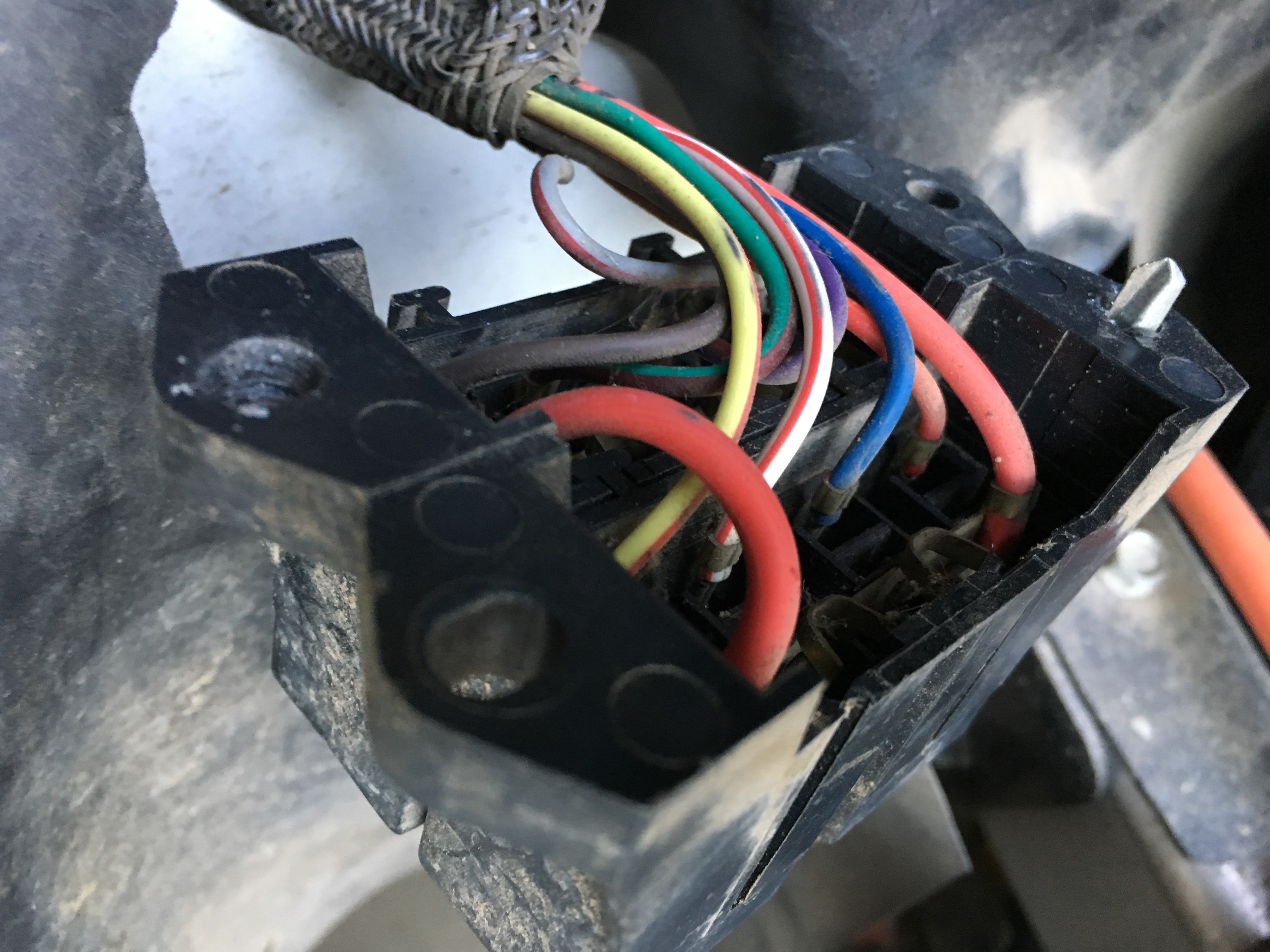
I have continuity between pin 12 and 13 on the bms. That seems likely to be the culprit right? Also likely the cause of the spark?
Ps charging using my 5v/2a wall wart is working. About 100mv per hour roughly. Put a fan on the wal wart and has stayed under 100*
I tried the wal wart trick too and ended up just using a automotive car charger and keeping my eye on it. The wal wart was a bit too slow for my situation. I can see it being useful for a stubborn cell though.
1 Like
Yes, I was afraid of that. My guess is that it has something to do with the switch being between cells.
Bummer! So I have two thoughts:
1 - Can this unit be repaired, or do I have to replace the whole thing?
2 - These seem awfully fragile. Is it possible to pay a little more and get a BMS that is less fragile?
All bms are fragile in that regard.
With the exception of balance only devices. The one I like only goes to 60 volts total.
Most likely one of the balance pnp’s are shorted. I can show you how to repair it, or can do it for $50 plus shipping.
Chargery warranties for most anything, but they’re safe, by requiring you to send it back. 
Chargery is the only one I find repairable.

These are the 24 balance transistors.
1 Like
The problem designing a bms is that it has to deal with near 100vdc. Yet each section is designed for less than 5vdc.
Anything that allows more than 5v or reverse voltage, even for a ms can cause damage.
A design is in the works uses ptc fuses in each lead. I don’t know if it can offer complete protection.
This is a modular bms. Each board is for 7s.
Stack 3pcs for a 21s bms. 4pcs for 22s to 28s.
Preset to default values for LiPo, LiFePo4, or LTO.
Add more boards up to 112 cells.
Any damage is limited to a $50 module.
Lcds are $25
Each lcd can display 24 cell voltages.
In theory presets can be change by BT or computer. Nobody has deciphered the Chinese yet.
Works fine as-is with no programming.


“A less Fragile BMS”. Yes I will take 2 please. It is a good Idea but I don’t think they exist yett. Sorry but I have messed up BMS’s b4 plugging into the wrong port or having the wrong cells hooked up out of order. It sucks messing one up so I feel for ya. But you only need to do it once and you think twice about just randomly plugging in and out. The BMS “So many’s ways to hook it up wrong and only 1 way to hook it up right”
If the BMS is turned off and everything is hooked up right I don’t think you should see or have any sparks when plugging in the JST plugs. Hope that helps. Like Dave says always check your JST plugs for voltage. 4,8,12,16 and so on and when you are sure check again, and then make sure you clearly mark you JST plugs so you don’t end up accidentally putting plug A into plug B’s location by mistake. “Happens to the best of us”
1 Like
OK! So I took a little break from working in the gem car. In the meantime Dave fixed my bms which is now working again(thanks Dave!). I will post more pictures and details later but for now I’m having a 12v problem, which I’ve had since switching to 96v lithium.
I don’t have any 12v at the fuse block, which means no lights, horn, wipers, turn signals, etc. I took the fuse block off and checked the actual feeder wire to confirm.
HOWEVER I do have 12v at the keyed relay (which on my car is hooked up to a cig lighter/auxiliary outlet).
Here is the relay I have 12v at

There’s something else under the relay. I do not have 12v there. What is it?

And here is a picture of my dc converters

This is a td off timer that keeps 12v circuits alive after turning key off. (from memory)
It looks like nothing is connected to the trigger (S1).
12v on 2 & 3.
Momentary connect S1 to 3 and 12v outputs to load (L). 1 & 3.
Remove connection from S1 to 3 and load stays energized for time 1-100 seconds.


Thanks @Inwo - My suspicion is that at some point in my cars past, somebody moved the 12v output from the relay I showed, from the S1 terminal on the timer, and installed an aftermarket 12v auxiallary outlet with that cable. The wire hooked up to my aux outlet looks the same as is hooked up to the S1 terminal on the timer in the picture you showed. That also explains a question I had (but didn’t ask), which was why my aux outlet wasn’t fused! Because it was never meant to actually have a load, it was just meant as a trigger to show key on/off.
However, that being said, all that has been the same since before my 96v conversion. Any idea why I’d be getting 12v at the keyed relay, but not at my fuse block (or anywhere else - including the Number 2 terminal on the timer)?
Is my next step to open up the DC converter and test inside of there? are there fuses inside the DC converter I should check?
Should not have to open converter. You say that 12v is available.
Converter has 2 12v outputs. One is always on, other is turned on by 12v signal going back to converter enable input.
12v goes thru charger interlock relay. Anything changed there?
I no longer use my interlock since I switched to the Delta Q charger. I connected the two wires together permanently, instead of going through the charger like they previously were.
I’m not sure what you mean by “One is always on, other is turned on by 12v signal going back to converter enable input.”
In looking at the wiring diagram I have, it looks like the fuse block wire goes directly from the converter to the fuse block without anything inbetween (if I’m interpreting it right). That’s the one that doesn’t have any voltage on it.

That’s not the converter in your picture.

OH ok! From reading the manual, it seemed like the PWB and converter were one in the same?? Clearly I’m confused though. I don’t see in the image you just posted where the fuse block gets power from. It seems an important troubleshooting fact to me that the fuse block doesn’t have 12v power, while the relay does. Is that not the right thing to be focused on?
7+8 power the fuse block when converter is turned on by pin 3.
9 + 10 are 12v, always on. For radio and key power through interlock.1 + 12 = 72v power.
4, 5, 6 12v ground.
