Perfect- Ignore the white wire for now I see the black and green going to the board at 3 and 4 which shows on the diagram. It looks like those are your wires.
If you connect those two wires does the car act differently? It looks like this circuit may sound the beeper when Key OFF but activate the direction solenoid when Key ON.
The diagram does not show the connection between the direction switch(key) and the direction solenoid.
I see the fwd-rev solenoids on the diagram now, they are just above the switch, controlled by pins 5&6, It looks like the board grounds them to operate? The beeper does come on in reverse, I took the solenoid off to inspect it, took it apart and it looks good inside, Now that I see how it works I will test it for operation when it is easy to get at and test voltage on control terminals.
Edit: or it applies power to the forward solenoid and grounds reverse solenoid? but it appears that the switch would ground the reverse solenoid also?
.
THAT makes more sense. It was just drawn this way to make it convenient electrically, not physically. [duhh]
I am having trouble understanding how the solenoids are controlled or how the board is told the key is on, This Gem doesn’t have a separate fwd-rev rocker switch like the newer ones do, you turn the ignition key to a fwd or rev position, The board has continuous 48 power and ground through fuse f1 and grounded at controller, pin 5 would also have 48 volts through the reverse solenoid until it is grounded, What grounds it? The board? pin 7 is marked main control and if you look at diagram it is fed power from the board, the ign. switch also shares this power source, as does the interlock circuit to charger. What tells the board to turn on? It does turn on and off but neither fwd or rev solenoids energize.
I suspect this diagram has some errors.
Since I don’t have one of these boards handy, Can you verify that P6 may be at -48v instead of +48v?
What do you find on P7? This feeds the center tap of the direction switch and the MC Since it comes from the same source as the MC.
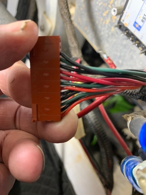
Does anyone know what kind of terminals this connector takes? This is where my problem is, I have to push the wire off to the side to get continuity on the terminal, I need to take them apart but would like to have some spare connectors, Thanks