I’ll get it out Fri.
What are your ideas for mounting?
Ideally, a punched double sided foam tape would keep light from leaking between leds.
That is not in my wheelhouse. 
It was all I could do to make the holes in the plastic case.
If that’s what it requires I can use some double sided tape and then use a Punch to make the holes for the display and then tape it down. What will the front side of the unit look like?
Nothing in the works for the display. It would fit in the same type box if you wanted.
It doesn’t need the circuit board. Discrete leds on leads will work.
I can look for a 10 led display.
I have a new plan that won’t require accurate machining. See picture. Sloppy holes on bottom, milled slot on top.
If there is cross-talk it would need tube over each sensor or punched tape. I just can’t get the accuracy for holes with punch or drill press.
I may redo this one before sending it. Part of my sensing problem was the holes not lining up perfectly.
Other side…
I just switched covers to the one with a milled slot.
It works scary good. Ran out of foam tape. Leaks a little, but still works.
Here’s a picture with tape down each side of slot. Needs a little more to be dust tight and light tight.
Can’t wait for the video if you get it working.
Dave come to think about it I have my lower dash drilled out to accept this LED display from my old charger
Perhaps I can fit your LED display in the same spot
Yes, we can make that work.
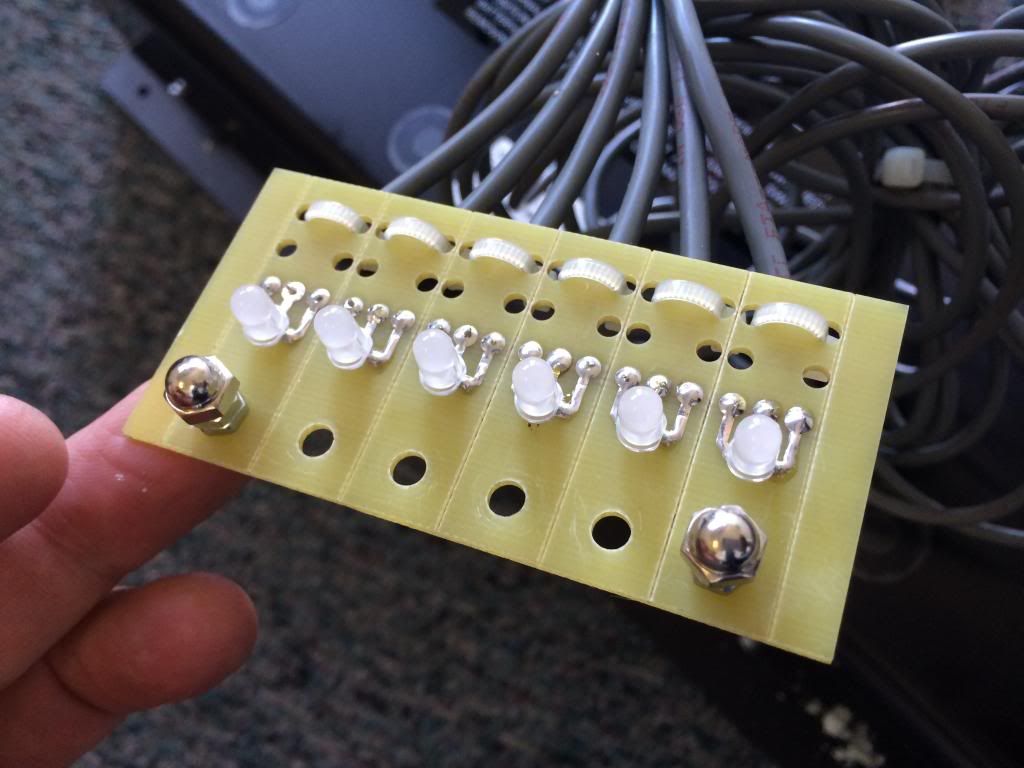
This one isn’t a keeper. Maybe you can pick 6 of 10 or drill 4 more holes.
The display end is just plain leds with 1k resistors.
How handy are you with solder?
I can show you how to put one together. Uses jst plugs from pick-up unit.
Do you have long ones or extensions?
I’m good with solder I have a nice Weller solder station with adjustable heet and real fine tips for Small PC board action
No problem for you to make a custom display then.
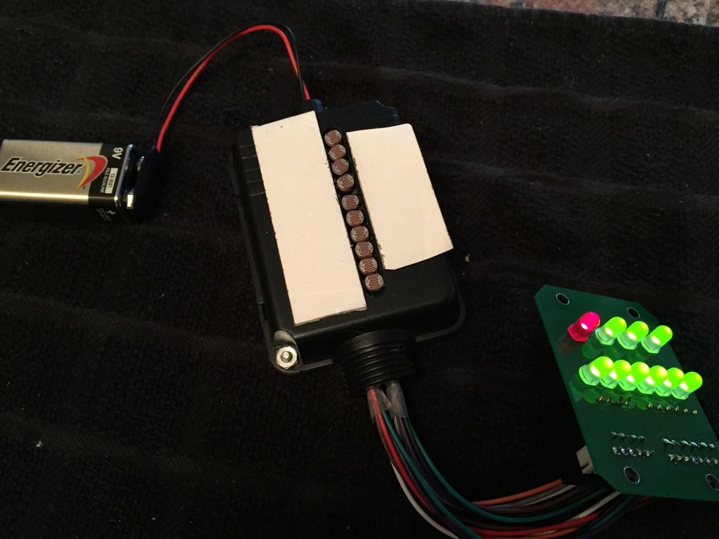
11 wires from sensor. A common and a wire for each led. All the electronics are in the sensor box.
Grant, project was on hold. Long cables came in today. Put another one together for testing.
I’m afraid I’ve given you a big job being my main beta tester. Maybe someone else wants to help out on this one.
Here is the new one with long cables.
Might try some potting on this one. Not sure how to do it.
Taking your lead on “tubes”.
Put short tubing over sensors. Then a bead of black rtv around them before pushing them thru the slot.
Rtv the squeezes between pcb and box holding everything in place.
Used round placeholders inside shrink tube while setting up.
After, the tubes can be trimmed.
Very labor intensive. I hope you can do some assembly if we get the bugs worked out.
I believe it needs a bead around the outside too!
You guys are ANAL. If you have a charger or battery problem (unlikely and infrequent) the cart will stop.
This doesn’t happen to most people and we don’t worry about it.
Why do you all live in FEAR?
Grant made me do it!:flypig:
OK, Now I understand:D
First off David is awesome! He makes things I can only think about. And if the status of charge was not important or where the delta q was in its charge cycle was not relevant then why did delta qnplace it on the side of its charger. Every modern electric car has a state of charge gauge why not a gem?
Most useful on the Gems with charger under the dash.
As far as my own goes, I can bend over as was suggested. (where have I heard that before?)
Hope for a little interest, to recoup some of my out of pocket $.
This project is lots of fun. Not on my car, blinking lights amuse me in my old age.
It may lead to other things. The circuit is universal in “repeating” an led display.
Free ship direct: $25.
After RTV set up and trimming with razor blade.