Hello all. I run an EV repair shop and recently accepted the challenge of dealing with a basket case GEM car LFP conversion. I work on Tesla’s and various hybrids regularly, but I’m completely new to GEM and other low-speed EV’s.
A couple of years ago, my customer purchased 12x Valence U27-12XP LFP batteries, wired them into a 72V battery pack by wiring 6 groups of batteries in series, with each group consisting of 2 batteries connected in parallel.
He purchased a Delta-Q QuiQ charger (P/N 912-7200). When he tried to connect the charger for the first time, it smoked and then ceased to light up again. He believed the charger failure was related to the charging algorithm and had the replacement charger programmed to algorithm 233. The project sat in his garage for about 18 months, and then they hauled it to my shop on a trailer.
I’m trying to learn everything I can about this application and possible compatibility problems before I connect the replacement charger and get the same result. It’s possible that something was wired incorrectly when the charger was first connected, but it seems like the battery pack he put together may create a lot of headaches. From what I understand, each battery has four internal cells and an internal BMS. He currently doesn’t have an external BMS connected, so I think his parallel/series battery pack might make it difficult if not impossible to keep the cells balanced.
My main question is this: Can this combination of batteries and charger create a reliable, low-maintenance battery system for this car or would it be better to start with a battery that fits the application better?
Any and all advice is appreciated. Thanks in advance!
Multiple bms in series is a bad idea. Even if they work, it is near impossible to trouble shoot, or verify all batteries are pulling their weight. Most 12v lithium limit series count to 4.
Mis-connecting a dq charger is hard to do. They are protected from over voltage and reverse polarity. The exception is the green interlock wire, if available. It is connected to B+ internally. Grounding it will blow internal fuse killing charger. White wire, if available comes from 3.2v logic input. Connecting to B+ could have bad result.
Unlikely, unheard of. Charger will not connect to load unless, all the “look ahead” are happy.
Exception is dci model. Built in dc-dc converter is connected direct to power leads. Big arc when connecting to battery. With everything else being overly complex, why not a soft start on the dc-dc converter?
Many members sell batteries tested to work in Gem car with specific needs.
We specialize in high voltage performance batteries. Some are too large for normal shipping after assembly, and are shipped in two-4 modules connected to a single bms.
Not being familiar with these batteries, I had to go look.
It happened to bring up this little tidbit:
[From BatteryHookup]
“These batteries have something that looks like a BMS but it is not. You will need to add a BMS to these. What looks like a BMS is actually a BMU which communicates to another system that will turn the battery on and off.”
I would wire each series 24s string to a bms and parallel the two bms.
I would also question your customer as to how he is planning to use this car and why he feels he needs such a large battery. Being an eL XD, is this some sort of commercial support vehicle that is needed for an extended shift without charging?
One set of the Valence batteries is roughly 2.5 times the capacity of a good set of lead acid batteries (assuming both sets are new). Does your guy really need all that capacity?
One set of 6 batteries is also 253 pounds that might not need to be carried around. That is like a whole linebacker!
You guys are awesome. Thank you for all of the valuable advice.
You’ve confirmed what I suspected - that this battery configuration is going to be a PITA even if I can get it to work, and that the capacity is overkill.
As for the application requirements, I think this is just a run-around the neighborhood fun vehicle with no specific requirements. He just got a great deal on these Valence batteries, and bought a bunch of them for this project because his lead acid batteries were dying and he wanted an upgrade.
If I understand you correctly, even if I simplify the configuration by putting just 6 batteries in series to create 72V output, it will still exceed the capabilities of most battery management systems, and create potential headaches from layering the internal BMS that balances the 4 cells in each battery with the external BMS that would balance the 6 batteries. Is that correct?
I also suspected that something more than the charging algorithm was wrong with the system when the first QuiQ charger gave up the ghost. Thank you for confirming that as well. I’ll do a thorough check of all wiring and verify connections before I hook up the replacement charger.
I’m going to recommend to the owner that we get a customer battery made specifically for this application. If he insists on trying to make these batteries work, should I be looking for a BMS that will handle 6 12V batteries in series? If I hook up the charger correctly and get it to push current into this monstrosity of a battery pack, what kind of symptoms and problems is he likely to deal with going forward?
This battery system will be as reliable as your wiring methods. It will be no different than one 24s battery in a single enclosure.
Most bms are not rated for parallel connection, but I have 4 jk bms in parallel with no issues. Worse case, one will shut down, and they will need to be balanced manually. I have not seen it happen.
I would like to have hands on the “bad” dq charger. I have seen them die for no reason, but rare to see one killed by user error. The exception being a dci delta-q, wich has a built in isolated 12v power supply. Mixing the two systems makes sparks. In theory it should not, as both systems are isolated, but an isolated system can hold a high static charge. IMO, the killer.
I gotcha. That does sound like a messy wiring project.
I believe they sent it in for a warranty replacement. I suspect I’m going to find something weird going on with the existing wiring that may help explain how they fried the charger.
On the datasheet for the batteries, it does list “Automatic Cell Monitoring and Balancing” as a feature. Wouldn’t that suggest an internal BMS, or are their other ways to make that claim without actually putting a BMS in each battery?
Thank you all for the helpful replies. I found out that my customer has a large supply of this particular battery that he can get for pennies on the dollar from work. That’s the reason he used them. I passed on your advice about wiring the cells directly, and he may pursue that route on his own.
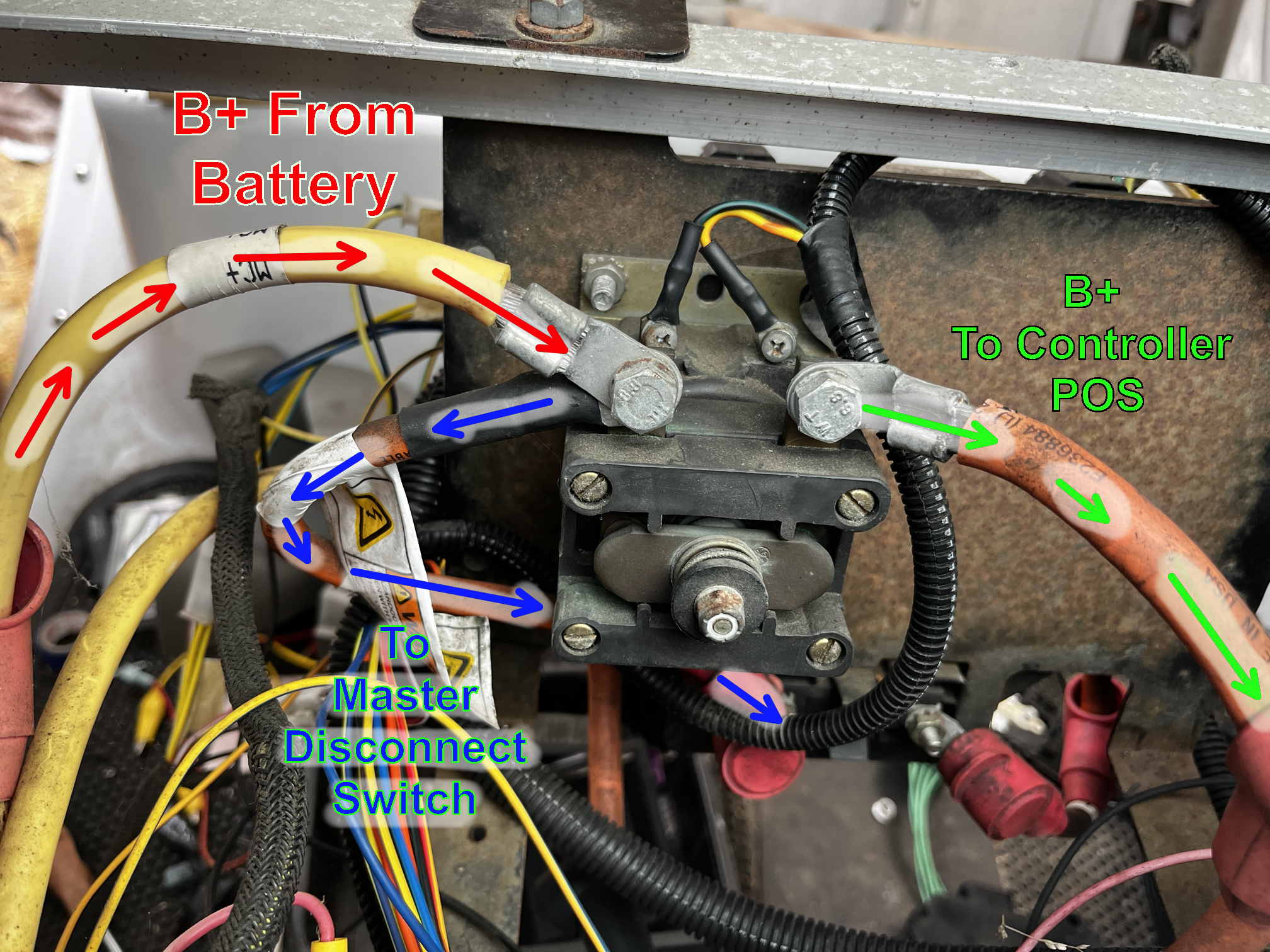
I’m connecting his new DeltaQ charger, and I noticed a bit of a conflict between what I’m seeing on the vehicle and what the wiring diagram shows. All of the diagrams show the main B+ wire from the battery pack going to the master disconnect switch, and THEN to the contactor that feeds the motor controller. However, the vehicle is wired with the main B+ wire going directly to the contactor, and the master disconnect switch only controlling power to the PSDM. I considered “correcting” this, then noticed that the terminals on the master disconnect switch were tiny compared to those on the contactor. I’m guessing that switch isn’t supposed to handle the amount of current that goes to the motor controller, and that the wiring diagrams are just wrong. Can someone confirm that so I can stop feeling like I’m taking crazy pills?
I don’t know what to tell you. He obviously knows way more than us.
and he may pursue that route on his own.
Somehow, I don’t have high confidence this is going to happen.
Again, Look into what that “onboard protection” actually is. The notes I read says this board was only part of a system that originally was connected to a central management unit that is not provided (which most likely did master switching) and other protection is needed to care for these batteries. I did not find any info that there was balancing(active or passive).
The main clue to look for is an empty plug on the board with a bunch of pins, but the output on this battery is still live and has output (no way to switch it off). Consider those boards inactive. This means the operator assumes the role of BMS. This is not impossible, but your original request in Post #1 was asking for a reliable, low-maintenance battery system.
Something that doesn’t get mentioned enough: Do it right, and it will work well. Do it wrong and it may/may not show you signs there is a problem brewing. Ignore those signs and it can burn your car down. Do it REALLY wrong and it will take out your garage and house. If you want to get a glimpse of the elephant hiding in the room → Tell your insurance agent you have a cart with a home brew lithium pack in the garage and see what he says.
===
the main B+ wire going directly to the contactor, and the master disconnect switch only controlling power to the PSDM.
What manual/diagram are you looking at? I suspect you might have a document labeled 2005-2010? If so, rename that as 2005 only. That shows the old/incorrect wiring path.
This is the my 09 was hooked up. I’ve always considered that one of the errors in the wiring diagram. You are correct, that little flippy breaker needs to be far bigger than 100a if it was to protect the main drive.
The DC Converter and Charger get hooked up to the far side of the Main disconnect from the battery pack. Using the factory wiring path, the switch needs to be ON for the car to charge, OFF when done and storage.
Thank you! My customer provided me with diagrams that were supposedly for a 2008 model, which must have used a master disconnect switch rated for much more current.
Something that doesn’t get mentioned enough: Do it right, and it will work well. Do it wrong and it may/may not show you signs there is a problem brewing. Ignore those signs and it can burn your car down. Do it REALLY wrong and it will take out your garage and house. If you want to get a glimpse of the elephant hiding in the room → Tell your insurance agent you have a cart with a home brew lithium pack in the garage and see what he says.
I 100% agree. The fastest and least expensive way to do ANYTHING is once. With a system that poses so many safety risks, there’s absolutely no rational reason to cut corners.
I was able to get the charger working (had to switch the B+ wire to the opposite post of the contactor from what the service manual described). I may end up wiring together two banks of 24 cells as you guys recommended above, but I’m concerned that the labor cost to do so may exceed the cost of buying a turnkey setup from one of you knowledgeable gentleman.
Thank you all again for the advice and assistance. This forum has been an incredible wealth of knowledge, and there’s nothing like hearing it from experts that can speak from experience. You guys rock!