Hello, how do I test the ride for fun motor? It is inoperable.
Thank you for any help with this MB
Hello, how do I test the ride for fun motor? It is inoperable.
Thank you for any help with this MB
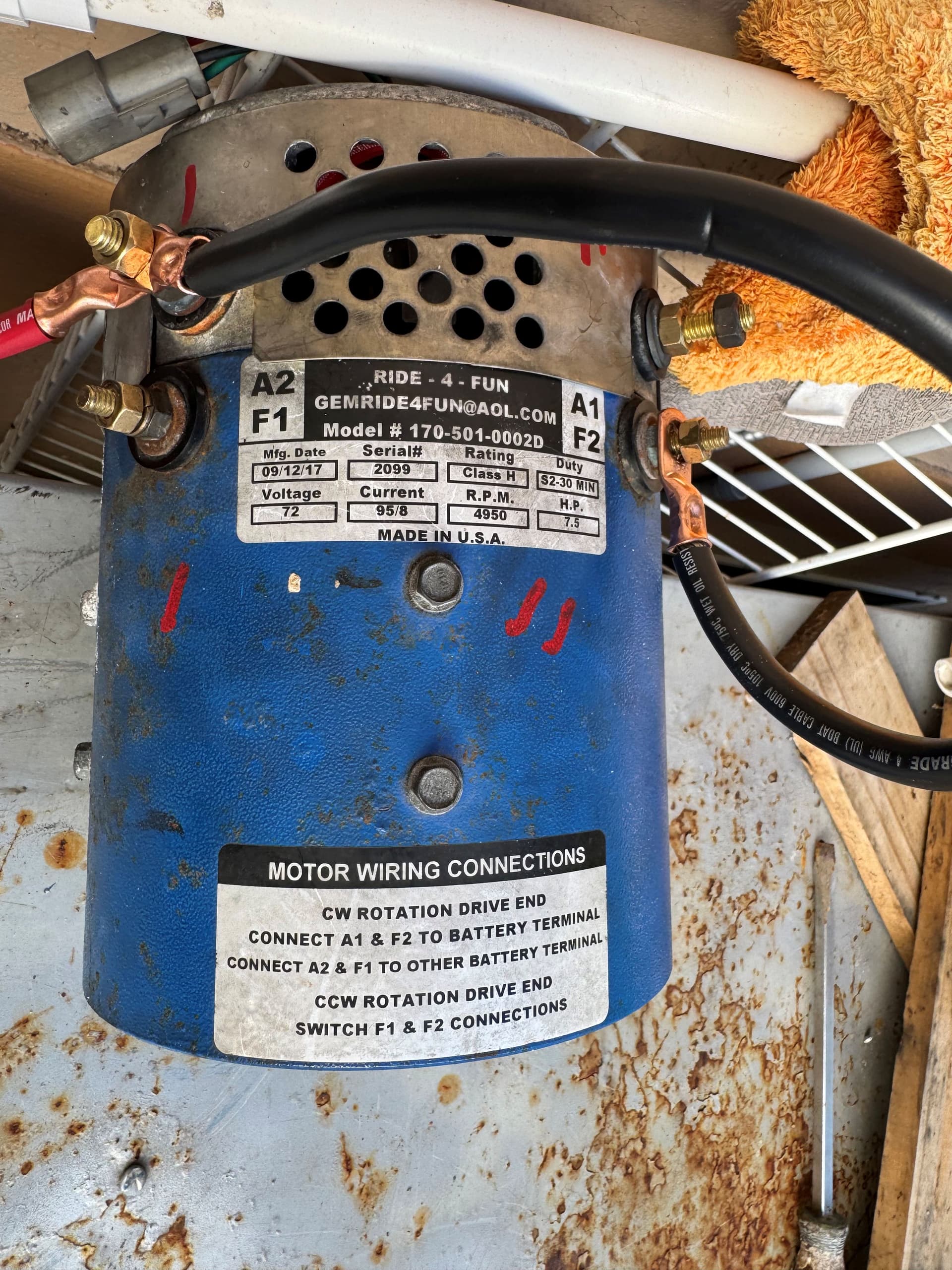
I have installed new bushes, and it passes the continuity test, I will apply 12 volts to A2 and F2 then ground F1. Is this the correct way to test the motor to see if it spins?
I just what to make sure I have wired the motor correctly before I apply 12 volts. Please see attached picture. Thank you, MB Please correct me, if I wrong…
Short answer- No. This motor will not work as you hooked it up. Don’t expect it to. It does not mean you assembled it wrong.
If it passed the continuity test I’d say you are good to install.
I don’t see the point of running it outside the car “just to test”. If it spins, it doesn’t really tell you much beyond that.
This is somewhat risky on another factor tho. If you broke this motor down to replace the brushes, I’m sure you noticed it only has one bearing on the coupler end. The coupler end is floating.
In other words-> This motor should not be bench tested without some support on the coupler end.
I suggest you stop what you are doing and we can discuss what you are trying to prove here.
This motor needs to be mounted on the gearbox to do a run test. It uses the bearings on the input shaft to support the floating (coupler) end. Mounted on your gearbox, you will be one step closer to running your car.
Hook it all back up the way it was and figure out if there is anything else wrong with your car.
I mounted the motor. Turn the key on load clunk from the contactor, press the go pedal and nothing…
I have 72 volts on the bottom two big gauge wires of the controller going down to the motor but no voltage from the smaller two wires when pressing the go pedal. Help please! Thank you, MB,
With loud clunk on the contactor, it is getting ready to go. Does it De-clunk at any time during this test?
I have 72 volts on the bottom two big gauge wires
These two big cables should be going to the A1/A2 lugs on the motor.
This voltage should vary with pedal press, then drop to (near 0v) when pedal lifted. (Drop is immediate)
Does it do this? (Verify Y/N?)
Motor will not run with (no volts) on the F terminals. Check to make sure the F wires are good. Take a V check right at the terminals on the bottom of the controller and that this V goes straight to the motor F1/F2 lugs.
I think it should detect an open circuit on the Field drivers and throw a code. Is it showing anything on the Dash display?
Otherwise, First guess says you need another controller.
Voltage on both a1 and a2 lugs on the motor are 72 volts regardless of pedal position.
There is no voltage at the bottom of the controller lug F1 or F2
Unfortunately, my bdi will not light up…
My contactor never dechunks during testing.
That is unlikely if main contactor doesn’t pull in. Where are your probes when testing voltage?
So, looks like it may be a bad controller like you said. So, moving forward I would like to know what wires going to the controller to check for power and grounds when key or key off before i send my controller out for repairs. Just need to make sure I get power and ground to the proper wires…
I also think that the controller could be the reason my bdi is dead. Is that possible??
So next question would be is where I should have power and ground to the bdi so I can confirm I have a bad bdi or electrical power or ground issue going to the bdi..
Ty for your help MB
I’ll try to step in for Byron. He’s on a road trip.
All that’s needed for bdi to come on is +72, to pin 1, and +72v to pin 2. One is from key circuit.
Check the small plug, 8 pin if T1 and 12 pin if T2 controller. Bdi is powered direct from this plug.
He’s on a road trip
Have not left yet. Just Busy.
Voltage on both a1 and a2 lugs on the motor are 72 volts regardless of pedal position.
This makes no sense at all. Describe how are you measuring this? (one probe on A1, the other probe on what?)
Unfortunately, my bdi will not light up
This makes it very tough to diagnose issues.
First test is always → When first power up [Main Battery Disconnect Switch to ON] (the turn switch under the back seat)
The BDI will light up, display a couple of numbers, then go out.
Does your car do this? Verify(Y/N?)
====
From your earlier post:
Turn the key on load clunk from the contactor
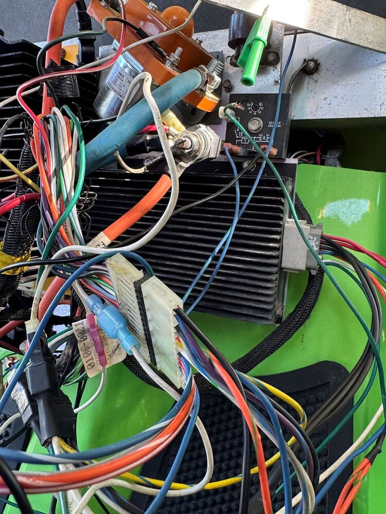
Can you post a few pics of the wiring around your contactor? Has there been any creative wiring on this car other than factory?
What is the history on this car?
How long have you had it?
When was it last running properly?
Ah, So the layers are starting to come off this onion…
Did you also happen to post this problem over on the FB forum?
You need to trace the wires that are powering up the Main Contactor/Relay. I bet they wired that directly to the key. This is why it is clicking (when it shouldn’t). This can be very bad on the controller.
You need to go back to the previous owner and smack him on the backside of the head.
I also think that the controller could be the reason my bdi is dead. Is that possible??
Yes. The BDI is powered directly off the controller. It is the first in a series of diagnostic checks when your car is not running. If the BDI does not light up when battery switched on, then you do not go past GO, You do not collect $200.
Too many hacks go immediately to the MC relay. They figure it needs to close first and the car will run. The MC is the LAST thing that closes as the car is about to run.
Okay then I guess I have my hands full…
Yes, they wired the contactor to the key switch
No, I have not posted this on Facebook.
I will try to get the bdi working so as we can properly diagnose my issue.
Any direction on properly wiring the contactor would be helpful. Thanks MB
Do you have the original wring diagram and the page of the DC Converter wiring update?
How well can you read those things?
I do not have original wring diagram and the page of the DC Converter wiring update..
I am very confident I can read a wiring diagram. Would be able to e-mail me this info please?
mb10190@gmail.com Thank you very much. MB
I will do a quick search on Google for this update converter wiring diagram.
I will send you a few documents to your email address.