The white disable wire connects to white from charger.
The Orange goes back to sensor on batteries.
Sensor is not used with lithium. The orange wire should be available near your bms. In that case, leave it connected up front.
Dave ,
On all the previous conversions I removed the temp sensor and ground the wire to battery neg . On this last one I left it the way was . Deltaq works fine . I think the charger wire goes thru the sensor and the other orange wire goes to ground so the charger is still seeing ground thru the sensor . Is there a reason we have to ground charger to neg and cant leave it the way the factory has it ?
The sensor has 10k resistance. It may work, but it may have issues down the road.
BMS will not start. I had it hooked up to the battery alone at first and it seemed fine. Now every time I switch it from ext to bat the screen comes on but there is no memory. It says:
LIPO
00 CELL
START
I can change it to different chemistry. I can change the cell count back to 20, but selecting start has no effect.
I have everything hooked up and wanted to check the pack one more time before throwing the switch. I put a 750A cutoff switch right between the battery and the fuse in the negative line.
Thoughts?
Tried a different cable for the com wire from brain to control unit and it worked. Must be some issue with the extended com cable… i will check for loose connection or damage.
The rj connector pins can be problematic.look at the gold spring contacts inside the sockets .
I’m looking to rewire the connection from the main BMS to the screen BMS. I need to buy a new wire and the results for rj45 seem to be network size connection and the connector for the BMS seems to be half that size. What size connector is it? Sorry, this is the only place I saw the connector called out. Thanks
Auto correct changed it to rj45. I meant the generic rj connectors.
Rj9 called handset cable or 4/4.
I plan to make a batch soon. I have shield cable for putting them together. Rj9 takes a special tool.
These are a bit confusing. The ones used here are the smallest variety.
Headset / handset 4P4C
RJ9 = RJ10 = RJ22
I just built a batch of 15’ using high quality shielded/stranded wire.
$25

Sorry for high price.  I have to drop all my own projects to have the time.
I did end up swapping the 4P4C wiring between the Chargery screen & brain. It works fine now.
Finally, I did throw the big switch. The spark & pop produced when the circuit was completed was not trivial. It actually very slightly blackened the contact. You may notice dielectric grease in the picture as I used on all critical connections. It would make me think twice about opening or closing the switch unless in an emergency. Is this normal? Is there a way to avoid or reduce the effect?

It was surprising and concerning but did no damage as far as I can tell.
- I flipped the main GEM breaker and everything came back to life!
- Successfully completed the first charge.
One note… when the charge is complete at just under 82v or 94%, I noticed that the GEM dash screen would periodically come on and show 99% and charging for about 30 seconds. This was concurrent with the green enable LED from the BMS. It seems that it is just topping off the charge. At this point any cells that were slightly above 4.1v (like 4.105) showed as “High”. Is this normal to cycle the charger on an off after reaching full charge? Do you guys put the charger on a timer or just leave it plugged in?

Anyway, at this point all the main systems in the box are installed. Battery, BMS, Inverter, Solar controller, 5v supply for LED lighting.
Next on my list:
- Dash work: 3 switches for lighting zones, inverter switch, solar switch. Also want to make some kind of mount or box for BMS screen & solar control.
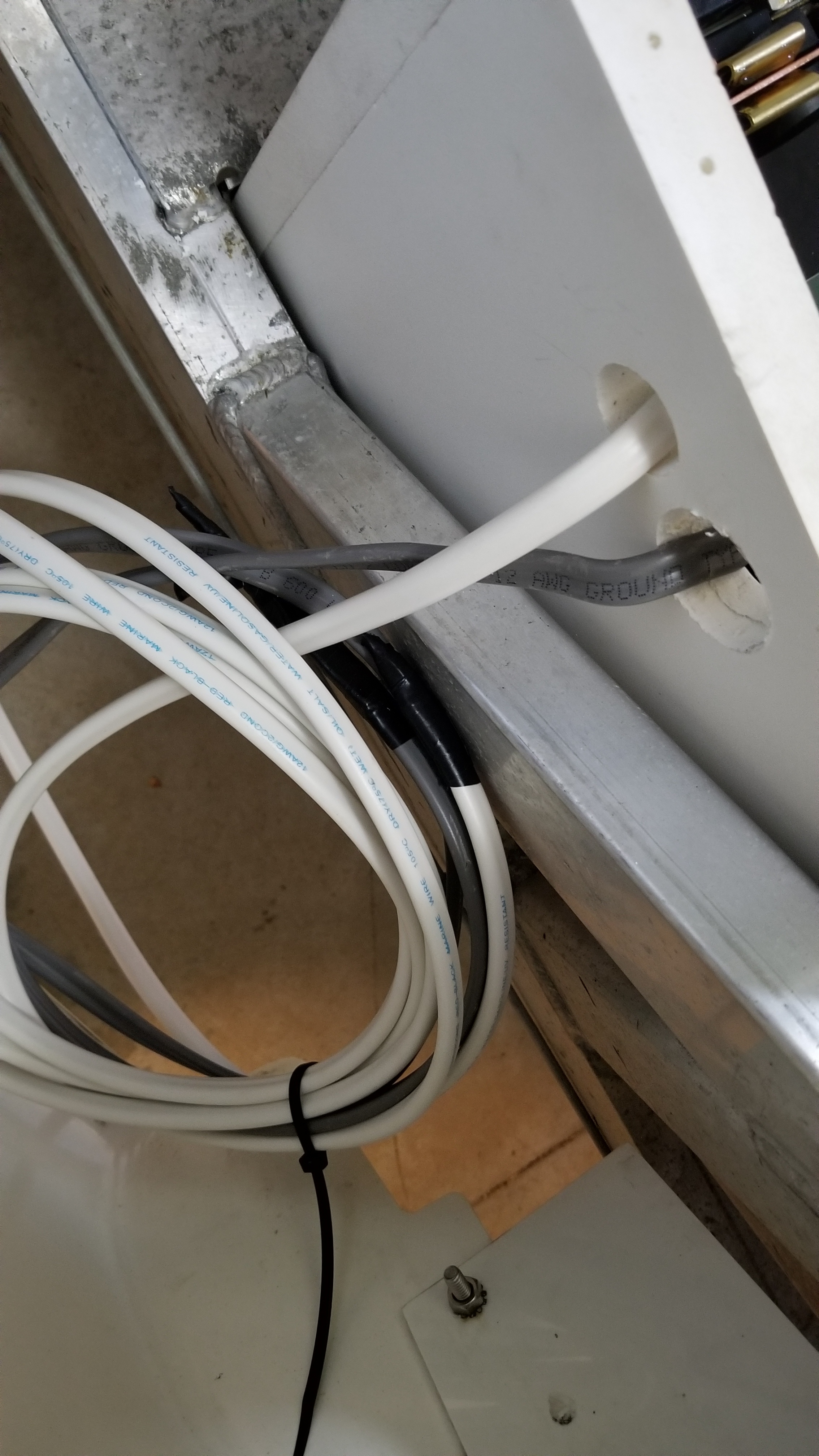
- 120 VAC wiring (outlets in cab, Bed / Max Box, external on rear end) you can see the gray UF cable dangling & taped.
- Install solar panel on roof rack. You can see the white marine grade 12ga DC cable dangling & taped. The solar control is powered by the panel so I did not get to power it up yet.
- LED addressable pixel strips and controller
- Add 4-pin trailer light wiring.
I will probably test drive it in the near future so I have a baseline. Then I will install the magic magnet and test. Finally I will swap the motor for the Ride-4-Fun motor.
Here are some current pictures


![20190519_235252|690x388]
(upload://z21UhDCUw5yBnyhLx3Jrg2QRzX7.jpeg)


What is the bms set to on the first few settings? The charge restart may be set too high.
I am not sure how to get into settings. Actually, I need to get a pdf of the manual for the BMS. The Chargery site is down.
What was connected to cause the surge? The inverter caps may be the reason. A precharge resistor across the switch helps.
1 Like
Everything was connected at the moment the switch was closed. Please elaborate on the precharge resistor (not something I am familiar with ore how to install).
By the he way, I just want to pause and say thanks again. The “free” expert support is indispensable.
Hold the start switch down to enter prog mode. Repeat to go back.
 I will try that later today after work.
You mean the main switch was on? Then it might be the controller, charger, and dc-dc caps.
I would have to research how to safely implement precharge. It is a resistor across switch contacts to slowly (few ms) charge any caps on the circuit.
Easy enough to do manualy, but it wouldn’t be failsafe. It is usualy done across a contactor using a timer.
You might google for ideas to see if it’s worth the trouble.
Off the top of my head, a 2 step switch. First the resistor then the main load. They may not even make such an animal.
I have not taken the time to read all of the above so excuse me if what I’m about to say have been talked about.
The P voltage needs to be Higher then the R voltage on the Main Menu
Example
P voltage = 4.10 volts
R voltage = 3.97 volts
R voltage is what your car will have to be at for your BMS to allow it to turn on the Charger.
Example your car is fully charged. 4.10 volts
You take your car out for a quick run and it’s at 4.0 volts. And you plug it back in. Because your car has not got to 3.97 volts (your programmed “R” value) the Charger will not kick on.
You have to take it out till your down below 3.97 volts THEN the BMS will call for a charge.
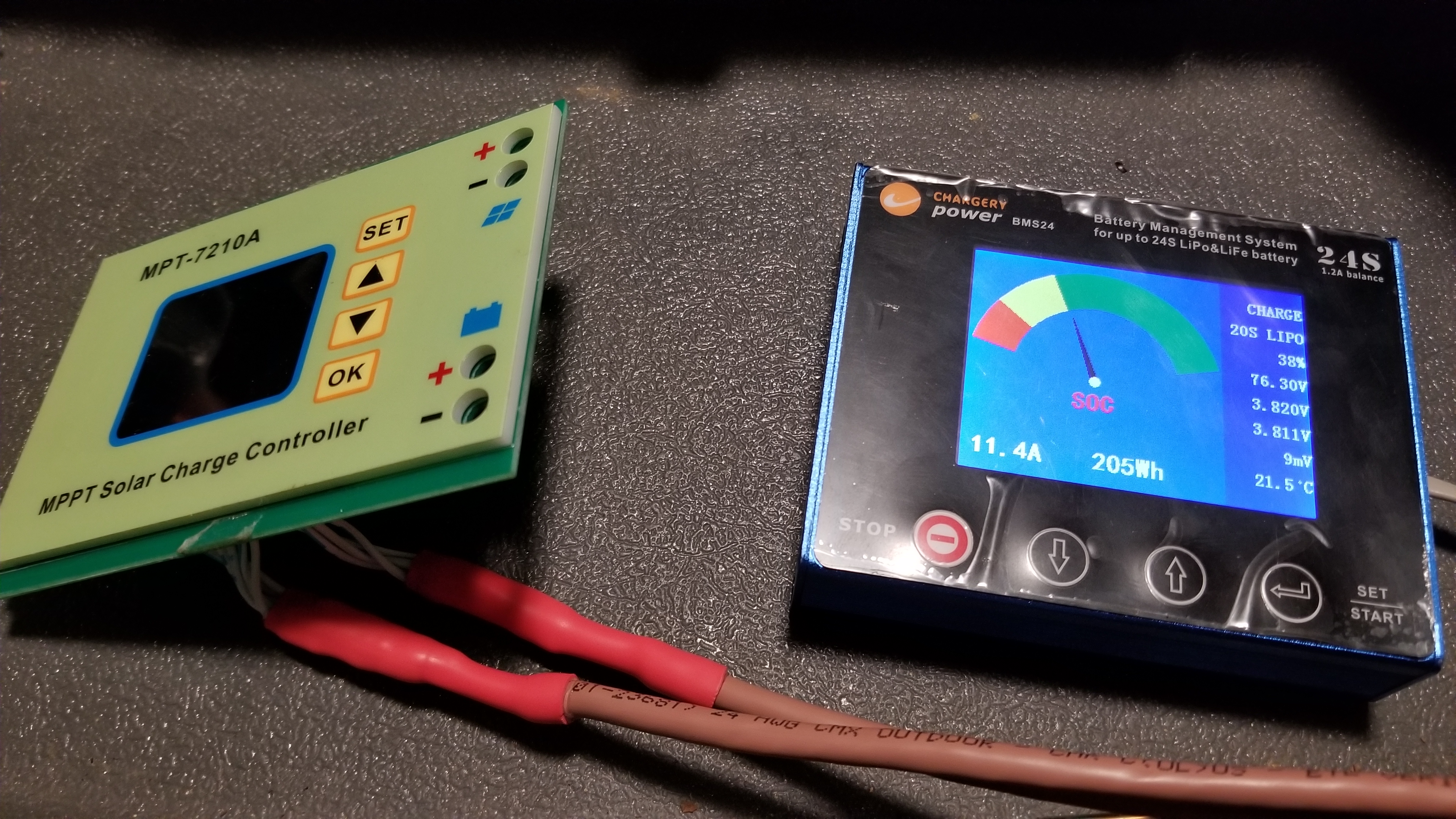
Try changing the P and R settings and then
Reset your BMS by turning off and then back on the Black power switch on the BMS and restart the BMS at the Display. You should the see the display saying CHARGE in the upper right corner like in this photo

You guys have been busy today. The car is going to be awesome. Thanks for the info on the Rj9. I just wanted a spare before I start chopping up the one I have.