The problem with bench testing motors is that it only has one bearing on the brush/comm end supporting the armature. The coupler end needs the support of the input shaft.
A quick search of the archives brings up the following. It is a different error code based around the Field Fets on a T3 controller, but it gives you an idea what you will be dealing with.
Since yours is a T6 the internals may be different so be flexible that it may not look like the pics in the threads. I can’t seem to find anything ref a T6 and a few others I have asked have suggested that since your label looks to be a remanufactured label from FSIP that it may be a typo or some custom config since you are in the UK?. You could try contacting them directly to see if they have any info in their records.
Post some pics when you get it open.
Best to identify the FET part numbers from what you find inside.
I plan to meet the owner at the vehicle tomorrow to check that they are ok with me opening up the controller. If they say ok, I will post pictures and let you know what I find.
One of the MOSFETs has clearly exploded. It has jettisoned two of its legs (still to be found), taken out a bit of circuit board, left sooty deposits over a significant part of the PCB and left its mark on the inside of the plastic case.
This discovery vindicates the decision to risk opening up the motor controller.
Aside from that the news is clearly bad.
I still need to use some solvent to clear away the sooty deposits, but the presence of surface mount components suggests to me that there were copper tracks on that side of the board. I suspect these are long gone in the proximity of the explosion and it remains to be seen if I can work out how to re-instate them.
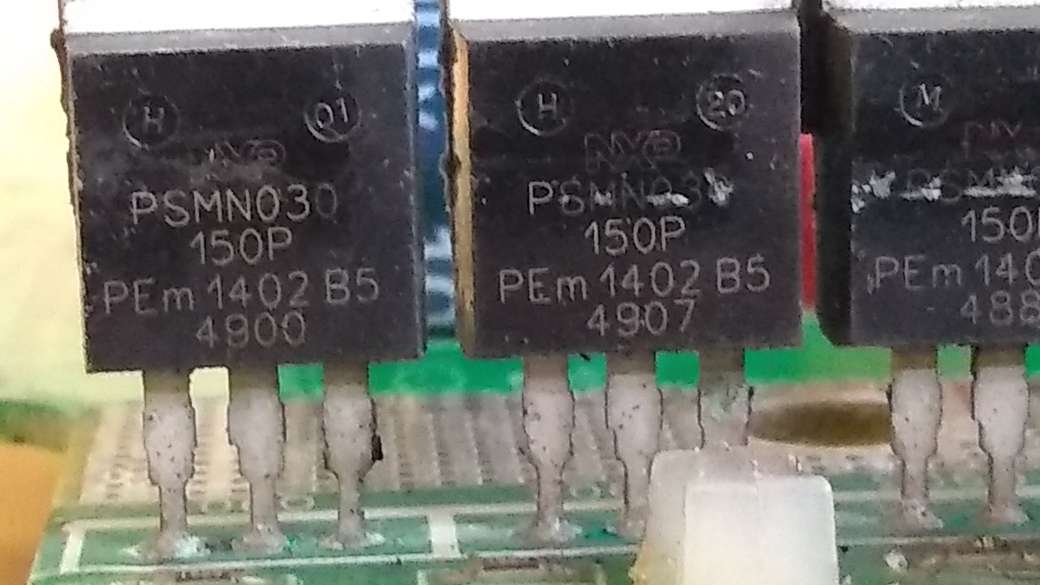
These markings differ only in the bottom row which I am hoping is a batch number.
At this stage, speculation might be moot as there is probably only one way this is going to go, but we’ve come this far so I will press on in the next post.
In the meantime here are some more pictures of the carnage.
The best scenario I can think of at the moment is predicated on the one remaining leg of the MOSFET being the gate.
With the MOSFETs being in parallel (I assume) it would seem that the drive to the undamaged MOSFETs has been affected. One possibility is that the whole drive circuitry has been destroyed. That will require more investigation.
But is there another less far-reaching possibility? Is it possible that the gate in the dead device has become shorted to the drain? There may only be one leg, but perhaps there is a circuit via the tab of the MOSFET through the heatsink. If the gates of all the devices are connected and driven together, is it possible that this dead device would be shorting the gates to all the drains? Might that stop all the MOSFETs from switching on.
If this were true then simply removing the dead device might allow the vehicle to work. If this were all true then in an ideal world, I would replace the MOSFET, but I cannot find it available anywhere. Perhaps an equivalent exists.
But for the purposes of proving the theory, perhaps the MOSFET location could just be left empty.
All this glosses over a couple of other major problems.
Tracks on the PCB are likely to have been destroyed .
Screws into the heatsink sheared off during the disassembly. These might have been current carrying.
I suspect that this is a conversation for the motor controller forum.
I have the controller board back at home on a desk and have made some detailed resistance measurements (let me know if you want more details). These lead me to believe that a total of eight of the fourteen output MOSFETs have died (gate shorted to drain).
My plan is to remove these damaged MOSFETs and then test the board back in the vehicle with a low current load, such as a mains light bulb. I am hopeful that the remaining eight MOSFETs will be sufficient to drive such a small load.
I’m a bit of a scaredy cat, and I don’t have a current limiting 72V bench supply, so I plan to build a two transistor current limiter and put that, along with a 5A fuse, in series with the battery connection. I’m hoping that will satisfy the dc-dc converter and controller electronics and provide enough power for a small load whilst significantly reducing the chances of an explosion.
The idea is that this is a relative low-cost way to find out if its worth going on.
If the planets align and the vehicle can light the light bulb, I’ll then try to track down some suitable replacement MOSFETs and fit them to the board. (PSMN030-150P do not seem to be available anywhere). Re-assembly would present another bunch of challenges.
I realise that much of this relies on things going my way, but its not looking like there is the budget for a replacement controller so I’m not sure what other options I have if there is a chance of getting it working.
The gates of the MOSFETs are driven by a couple of (what look like) transistors via a common series resistor and a 68 ohm resistor on each gate. The common series resistor is labelled 3R32.
One of the “suppressor” (?) capacitors (there are a bunch of these in series with a 3R3 resistor dotted around the board sitting between the A2 output and GND) had shorted and one of the 3R3 series resistors was open circuit (though I might have damaged this in messing with it).
There was also a 3R3 resistor on the low current board on the output of the gate drive circuitry that was showing kilo ohms. I nicked one of the suppressor resistors to replace it.
With the damaged stuff removed, I inserted a lone IRFB4410ZPBF MOSFET - not enough to drive the motor, but enough to drive a light bulb (as you suggested) to validate the the system before investing in more MOSFETs.
All this has taken about five weeks on and off, but if I connect up the controller boards to the buggy, I can now control the brightness of a light bulb using the pedal of the buggy. [If I press too hard, I see error 57 - “output current too low”. Not surprising.]
I would hope that if I order and fit another 12 IRFB4410ZPBF MOSFETs (only rated to 100V but hopefully that is enough) then I might be able to drive the motor.
I won’t be out of the woods then as I still need to try to rebuild the controller into its housing, fixing all the things that got broken when it was disassembled.
drill 6mm blind hole (orange) for insulator (black)
separate
drill 9mm depression (red) on inner sides of metal bars for electrical clearance
remove some solder resist from the top of PCB for screws to make contact with copper plane
Cleaned off visible corrosion and metal bars making electrical contact.
Re-assemble controller into case, reattaching temperature and current sensors, and mount in buggy attaching POS and NEG cables. Restore motor to buggy and attach field and armature cables.
Turn master switch and “ignition” key on, and gingerly press pedal to see wheels move (albeit up on axle stands). No error codes.
I haven’t dared to run it for more than a few seconds or drop it off the axle stands yet. I still need to use bathroom sealant to seal the controller case against the elements.
Nice job! Even better that now it is working.
It might be too late to offer the thought that leaving two FET’s out might not be the best idea, but I guess if they take it easy you might get away with it.
Depending on the damage, It might be better if you mounted the components as they were normal, and jump wired the tabs over to the nearest trace or neighbor solder points.
Good thread for me to bookmark.
Sorry, I may have missed some things, but want to clarify this statement.
The same and all “A” transistors are used in both directions.
Direction is controlled only by two sets of “F” transistors.
Again, sorry if this was covered later in the thread.
And double sorry if I’m wrong!
Yep, I am uneasy about compromising on the capability of the drivers. But then I looked at the numbers and there must be something that I am missing. The datasheet for the previous PSMN030-150P MOSFET shows 55.5A limit for the drain current for each device. The total parallel capability of the original 14 MOSFETs would seem to be be around 800 amps whereas the fuse in series with the batteries is only 250 amps. That seems like overkill to me so I must be missing something.
The datasheet for the replacement IRFB4410ZPBF quotes 97 amps for the same parameter so the twelve IRFB4410ZPBF might add up to about 1150A of current capability. The on resistance is also lower (9 mohms compared to 30 mohms) so that should reduce power dissipated.
Overall, based on the datasheets, I was hopeful that twelve IRFB4410ZPBF could comfortably do the job previously done by the fourteen PSMN030-150P (hopefully the 100V limitation of the IRFB4410ZPBF is not an issue).
I recognise that datasheets are not the final word but fourteen PSMN030-150P in parallel seems like overkill. What am I missing?
Yes, I think you are correct on all points. I would describe the field drivers as being in an “H” configuration capable of reversing the polarity of the field current to reverse the direction of the motor.
I drove it gently up and down the site for about 2 miles in total yesterday. My only concern was that motor was rather warm at the end of it. Is that normal? Might the bearings need lubricating or could it be electrically generated heat?
I saw a few error 11 (“Accelerator pedal was pushed when the car was first turned on”) on key on, which might have been me resting my foot on the pedal. If I get reports that they are still happening, I can look at the electricals of the pedal.
There was a bit of an “electric motor” smell (reminded me a bit of model trains) at the beginning. I am hoping that was just due to all the lubricant that ended up on the commutator after working on freeing up the brushes.
If the original failure was due to water ingress into the controller (there was a lot of water beads on the circuit boards when I opened it up), then it would seem to make sense to properly seal the controller case. It might make any future disassembly more challenging but I’m planning to play my “did my bit - someone else’s turn” card if any more problems arise.
Most of the fixing bolts that screw into aluminium are badly corroded so I might look to source replacements for them. Is zinc-coated better than stainless steel for aluminium?