Greetings, all.
I’ve built a couple of electric gokarts over the past year. The first had a shunt-wound motor and controller to match, and reversing was accomplished by throwing a switch, which basically told the controller which direction you wanted the motor to turn. No contactor was required - the controller just reversed the polarity of the motor field. (ADC motor, Sevcon Millipak controller)
The new, improved, more powerful, and faster kart uses a simpler controller (Alltrax) and a D&D series wound motor. At first, I didn’t want to spring for a reversing contactor, so I settled for forward-only, and reverse was done by pushing the kart.
Two things led me to purchase a reversing contactor, finally. First, I’m sick of pushing. Too low tech. Second, I want to try my hand at “J turns”. (If you’re from the US and over 40, you might know this maneuver as the “Rockford”)
So my contactor arrived a couple of days ago. It looks like this:
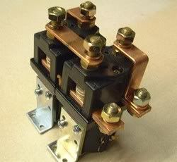
What you don’t see in the photo is that the back row of contacts are “mirror image” of each other, so there’s a terminal back there that doesn’t show in the photo. Also, the bar on the nearest terminal is common across the bottom of the front side - it connects the bottom near terminals of both relays.
The solenoids act on two bars of copper with contacts. These bars go from lower left to upper right in the orientation of the photo. Got all that? Good. This thing comes with no instructions or diagrams, and it took me about an hour to figure out where you much connect the battery and motor terminals. Let’s call the coils “X” (the far coil) and “Y” (the near coil). Battery terminals (ok, the terminals from the controller, but you get the idea) will be called “B-” and “B+”. The [edit] field [/edit] connections are “M1” and “M2”. A diagram follows:

Four states of the relays are shown. The diagram is the view from the top of the contactor. Heavy lines are those copper bars you see, and light lines are connections as a result of the relay contacts. “X” means the X coil is energized, “X bar” means it’s not. Likewise for Y.
If you’ve got all this so far, you’ll see that when the coils are in the same state, the [edit] field [/edit] is shorted - either to B- or to B+.
[Edit 12Feb2008]
Question deleted. Post left for informational purposes.
The terminal marked "B-" should actually connect to one side of the armature. The other side of the armature goes to battery negative. The "M1" and "M2" terminals go to the field windings. In this way, the reversing contactor will reverse the field with respect to the armature. Simply connecting the motor and armature in series and then to the "M1" and "M2" terminals will result in a motor that can be powered in one direction.
I’ve got the kart all wired up with reverse now. I’ve got to get in some more practice on my J-turns, though. 
[end of edit]
-Mark