# AC motor /Lithium Install on 2013 Gem E4 with no PDSM(basically rolling chasis)
**URL:** https://community.electricforum.com/t/ac-motor-lithium-install-on-2013-gem-e4-with-no-pdsm-basically-rolling-chasis/26963
**Category:** GEM Forum
**Created:** [September 21, 2023, 2:11pm UTC](https://community.electricforum.com/t/ac-motor-lithium-install-on-2013-gem-e4-with-no-pdsm-basically-rolling-chasis/26963 "2023-09-21T14:11:15Z")
**Posts on this page:** 20
**Page:** 1
### Author:  [@clubcmc](https://community.electricforum.com/u/clubcmc)
#### Post date: [September 21, 2023, 2:11pm UTC](https://community.electricforum.com/t/ac-motor-lithium-install-on-2013-gem-e4-with-no-pdsm-basically-rolling-chasis/26963/1 "2023-09-21T14:11:15Z")
Hola! I was finally able to pick up my battery, motor, controller and charger and have a couple of days to work on the install. Big thanks to @LithiumGods for the charger and the Battery and @BadBrad for the motor and the controller, which I believe was made by @Inwo
If you saw my original post [Newbie just bought what appears to be a frankenGEM...Is it salvageable? to upgrade?](https://community.electricforum.com/t/newbie-just-bought-what-appears-to-be-a-frankengem-is-it-salvageable-to-upgrade/26737) I was unsure if this was a complete mix match of parts, but it turns out all the frame, body, etc are all of the same VIN and the previous owner just put in golf cart parts to make it run(very slow).
I am usually terrible at documenting my restorations, but I want to try and catalog it here in case someone decides to take on a complete rewiring of a GEM like me. I searched on this forum and can’t find much info(especially no pics) of what goes where in a setup like this.
I have secured the motor, heatsink, controller, charger, and battery. I have 2 fuse panels(one for 12v(always on and one for with the ignition). Now I would like to know which wires go where. Pictures for reference coming…
---
### Author:  [@clubcmc](https://community.electricforum.com/u/clubcmc)
#### Post date: [September 21, 2023, 2:24pm UTC](https://community.electricforum.com/t/ac-motor-lithium-install-on-2013-gem-e4-with-no-pdsm-basically-rolling-chasis/26963/2 "2023-09-21T14:24:30Z")

@LithiumGods did tell me how to connect the + and - wires from the charger, but I want to highlight it here, so I get it right and other can view it.

I saw @grantwest install of the circuit board from the controller and the box he made. I was wondering if it is necessary to place the circuit board on top of the charger of if I could place it behind the plexiglass? Also not sure what plugs into this circuit board.

I am thinking of securing the 12v fuse panels in this position. I am not sure where I need to be running the wires from, so I am waiting to get the cleanest install.
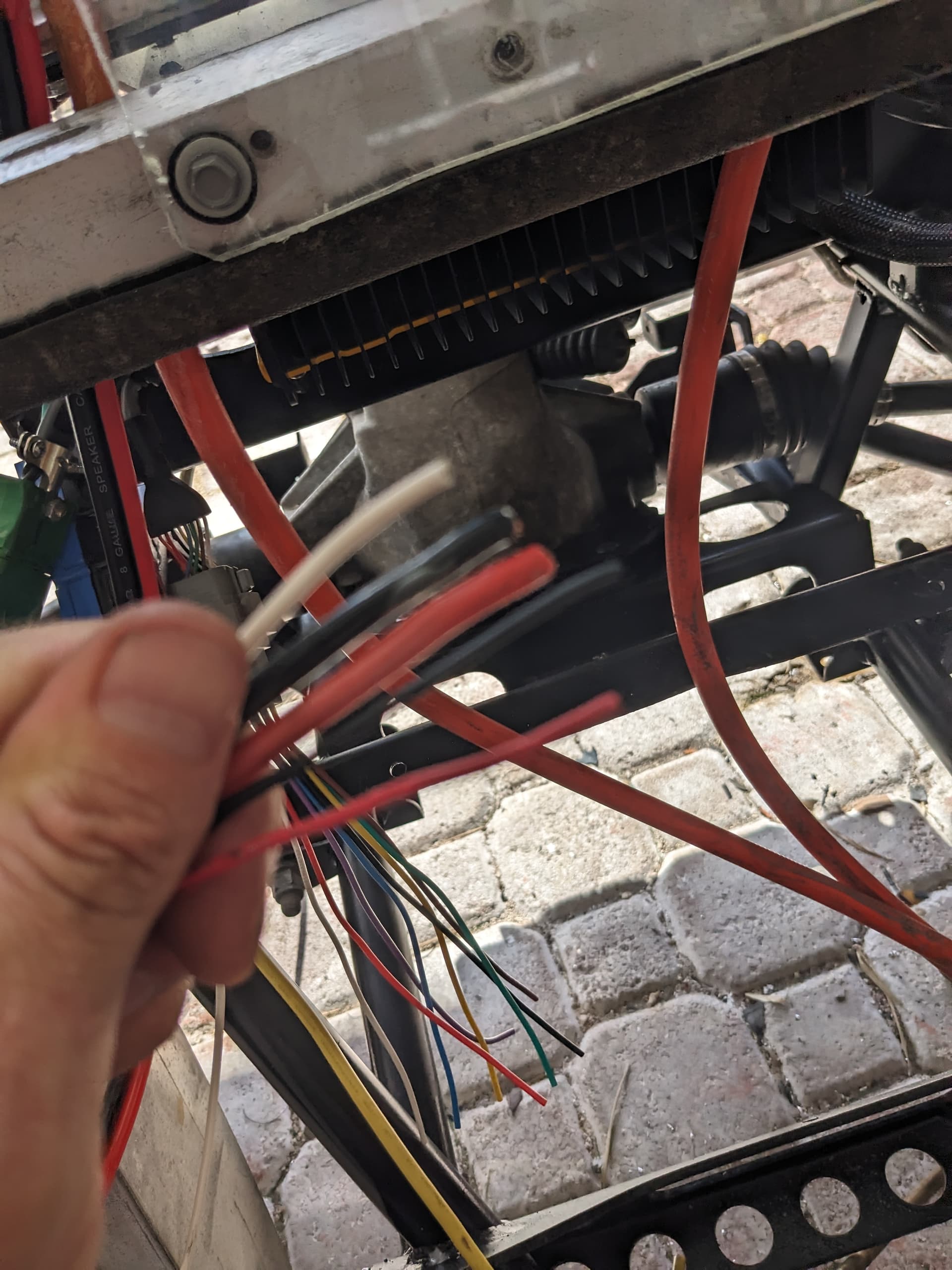
I checked the charger manual, but I could not tell which of these wires need to run.

There was some reference on these wires, but since my setup is sans computer, not sure which ones I need to run.
I am mostly interested in getting it to run and I can work on the the 12 volt accessories later.
Thanks for any input/expertise and hopefully this helps any other idiots, I mean people who want to go this route.
---
### Author:  [@Inwo](https://community.electricforum.com/u/Inwo)
#### Post date: [September 21, 2023, 3:10pm UTC](https://community.electricforum.com/t/ac-motor-lithium-install-on-2013-gem-e4-with-no-pdsm-basically-rolling-chasis/26963/3 "2023-09-21T15:10:42Z")

---
### Author:  [@Inwo](https://community.electricforum.com/u/Inwo)
#### Post date: [September 21, 2023, 3:45pm UTC](https://community.electricforum.com/t/ac-motor-lithium-install-on-2013-gem-e4-with-no-pdsm-basically-rolling-chasis/26963/4 "2023-09-21T15:45:43Z")
If a pc adapter board came with it, probably not used.
Wire controller and motor as per example car should run.
Use contactor 1 pin 3&4
Throttle pin 22, 34, and B-.
Key sends B+ to pin 1. P6 not needed.
18, 19, 30 are only switches prgrammed (needed).
If it was a kit, motor will plug in.
3 phase wires to motor can be 4 or 2 awg.
Can bus wires for programming may be same plug as motor sensor. Check pin numbers.
---
### Author:  [@Inwo](https://community.electricforum.com/u/Inwo)
#### Post date: [September 21, 2023, 3:49pm UTC](https://community.electricforum.com/t/ac-motor-lithium-install-on-2013-gem-e4-with-no-pdsm-basically-rolling-chasis/26963/5 "2023-09-21T15:49:01Z")
I see the pcb now. It won’t matter to leave it, but you will be connecting to terminals, as you have no 23p plug.
Don’t let board short to frame. Do connect to B-.
---
### Author:  [@clubcmc](https://community.electricforum.com/u/clubcmc)
#### Post date: [September 21, 2023, 4:35pm UTC](https://community.electricforum.com/t/ac-motor-lithium-install-on-2013-gem-e4-with-no-pdsm-basically-rolling-chasis/26963/6 "2023-09-21T16:35:00Z")
Really appreciate your assistance. I know nothing of these setups.

I secured the PCB to the plexiglass(shielding from the frame, used a jumper to B-. That work?

Just trying to understand the basic line flow. From controller PCB to fuse panel(always on?) where do the charger lines intersect in this circuit.

Not sure what this 2 pin is for, If I need to make male for it.
---
### Author:  [@Inwo](https://community.electricforum.com/u/Inwo)
#### Post date: [September 22, 2023, 12:17am UTC](https://community.electricforum.com/t/ac-motor-lithium-install-on-2013-gem-e4-with-no-pdsm-basically-rolling-chasis/26963/7 "2023-09-22T00:17:17Z")
Numbers on the board relate to the controller pins.
Look at the diagram above and ignore the pcb function. Its 9nly used as a connection point in your case.
Wire a key switch from B+ to pin 1 to power controller.
Wire a selector switch from B- to pins 18 and 30 direction.
Motor encoder 4 wires should plug in.
Motor thermistor connects to pin 33 and B-.
Pins 13 and 24 are for programming.
22 is throttle pot wiper
high side pot pin 34 = 12v
B- low side pot
Pin 19 is from throttle switch. It must connect to B- when throttle is actuated.
Power is routed to controller B- and B+ with B+ going through line contactor.
Main contactor 72v coil connects to controller pins 3 and 4.
Connect 3 phase from controller m1 m2 m3, to motor power input.
Random order is ok if motor phases are marked differently.
35p connector is numbered. Look closely.
---
### Author:  [@Inwo](https://community.electricforum.com/u/Inwo)
#### Post date: [September 22, 2023, 12:21am UTC](https://community.electricforum.com/t/ac-motor-lithium-install-on-2013-gem-e4-with-no-pdsm-basically-rolling-chasis/26963/8 "2023-09-22T00:21:26Z")
Ks1 is 72v from key.

---
### Author:  [@Inwo](https://community.electricforum.com/u/Inwo)
#### Post date: [September 22, 2023, 12:26am UTC](https://community.electricforum.com/t/ac-motor-lithium-install-on-2013-gem-e4-with-no-pdsm-basically-rolling-chasis/26963/9 "2023-09-22T00:26:22Z")
Just noticed p4 is not pinned.
Adding a wire is best, but.
Constant fused 72v+ can go to one side of coil, as gem was originally wired.
Then mc3 to other side of coil. Pin 3
---
### Author:  [@Inwo](https://community.electricforum.com/u/Inwo)
#### Post date: [September 22, 2023, 12:29am UTC](https://community.electricforum.com/t/ac-motor-lithium-install-on-2013-gem-e4-with-no-pdsm-basically-rolling-chasis/26963/10 "2023-09-22T00:29:02Z")
Picture of throttle you are using? Do you have wires to reach pcb?
5 wires required. Pot high, low, and w.
2 wires from no. fs1. One to b- and one to fs1 pin 19
---
### Author:  [@clubcmc](https://community.electricforum.com/u/clubcmc)
#### Post date: [September 22, 2023, 1:07am UTC](https://community.electricforum.com/t/ac-motor-lithium-install-on-2013-gem-e4-with-no-pdsm-basically-rolling-chasis/26963/11 "2023-09-22T01:07:21Z")
Awesome. Appreciate it! I now see the indicators on the PCB, was difficult to see behind the wires. I will have some time tomorrow to link them up. The throttle is one I have not seen before(not the welder pedal I’ve seen in Gem pics.) It does have wires. Actually alot of extra wires as the previous owner put in a full new wire harness as he had to get all the 12V from the back battery bank. Just want to make sure I take my time to get as clean of a run as possible. Only have a couple of days to get it rolling.
---
### Author:  [@Inwo](https://community.electricforum.com/u/Inwo)
#### Post date: [September 22, 2023, 1:10am UTC](https://community.electricforum.com/t/ac-motor-lithium-install-on-2013-gem-e4-with-no-pdsm-basically-rolling-chasis/26963/12 "2023-09-22T01:10:31Z")
Ohm out the throttle. 2 wires are isolated from the 3 pot wires. They will connect with first press of throttle. Mark those two fs1.

---
### Author:  [@clubcmc](https://community.electricforum.com/u/clubcmc)
#### Post date: [September 22, 2023, 12:16pm UTC](https://community.electricforum.com/t/ac-motor-lithium-install-on-2013-gem-e4-with-no-pdsm-basically-rolling-chasis/26963/13 "2023-09-22T12:16:12Z")
The accelerator that the previous owner put in is not from a gem(he actually cut a hole in the tub and a cross member to install), it was working before so I decided to keep it for now. It has the same basic wiring coming out, +, - , and the 3 Pot connections(only the high and low were connected, so I should add the mid, I’m assuming). Unfortunately I left the switches(and the key portion of the switch) in the steering cover I sent to the painter, so now I have to decide if I am going to buy some overpriced switches to get this tested before I fly out.
Here is a pic of my accelerator for reference

When you say, 2 wires are isolated from the 3 pot wires, does that mean that they cannot be connected within a 4 pin connector. That is how they are now. The 2 wires are the + - for the throttle(that would be the + to the fs1, and the - to B- ?
Wish I had this diagram and knew the layout of the PCB when I got it, would have been able to get a lot further with fewer questions. Thanks!
---
### Author:  [@Inwo](https://community.electricforum.com/u/Inwo)
#### Post date: [September 22, 2023, 1:31pm UTC](https://community.electricforum.com/t/ac-motor-lithium-install-on-2013-gem-e4-with-no-pdsm-basically-rolling-chasis/26963/14 "2023-09-22T13:31:17Z")
> [@clubcmc](#):
>
> The 2 wires are the + - for the throttle(that would be the + to the fs1, and the - to B- ?
Yes.
Connector type doesn’t matter.
> [@clubcmc](#):
>
> 3 Pot connections(only the high and low were connected
It may look that way but the center pin (W) was connected. It is the only one that changes resistance.
You can connect throttle pot the same using two wire pot. Controller needs to be reprogrammed for the new throttle in any case.
For two wire throtttle, connect 34 and 22 together and to high side of pot. (wire 1)
Low side of pot to B- ((wire 2)
P19 connects to switch. (wire 3)
Other side of switch to B-. (Wire 4), can be connected same place as the pot B-.
Connected this way there will only be 3 wires to throttle. B-, pin 19, and the one to P22/P34.
---
### Author:  [@Inwo](https://community.electricforum.com/u/Inwo)
#### Post date: [September 22, 2023, 1:37pm UTC](https://community.electricforum.com/t/ac-motor-lithium-install-on-2013-gem-e4-with-no-pdsm-basically-rolling-chasis/26963/15 "2023-09-22T13:37:56Z")
Connect throttle first to test.
Then connect B+ to P1 of controller to power up.
Test #1:
Measure P19. It should be about 36v, going to zero when pressing throttle.
Test #2:
Measure P22. I need voltage at idle and voltage at wot.
Send me controller or someone with DVT needs to set up throttle.
@MikeKC
2 wire throttle will be 0-12v, I think. Do you think this controller will run as it is? I just set one up for an Anvil. That was about the range. IIRC
0-10 or 0-11 maybe. I can look it up.
---
### Author:  [@clubcmc](https://community.electricforum.com/u/clubcmc)
#### Post date: [September 22, 2023, 3:22pm UTC](https://community.electricforum.com/t/ac-motor-lithium-install-on-2013-gem-e4-with-no-pdsm-basically-rolling-chasis/26963/16 "2023-09-22T15:22:24Z")
Wire a key switch from B+ to pin 1 to power controller.
**Not sure what is the Power controller(Is that the power B+ terminal on the motor controller?)**
Wire a selector switch from B- to pins 18 and 30 direction.
**I have wire in the Fwd(18) and Reverse(30) wires. I also need to route a B- to both 18 and 30? Is it ok to use the B- terminal on the back of the PCB?**
Motor encoder 4 wires should plug in.
**In**
Motor thermistor connects to pin 33 and B-.
**This had a plug as well.**
22 is throttle pot wiper
**For windshield Wiper? Mine does not have one.**
high side pot pin 34 = 12v
**Not clear on what High side is, but would this be what I could use for 12v fuse panel(always on, or only when switch is turned?)**
B- low side pot
**Not clear on which pot you are referencing**
Pin 19 is from throttle switch. It must connect to B- when throttle is actuated.
**So run a B- to 19 in addition to line from the throttle?**
Power is routed to controller B- and B+ with B+ going through line contactor.
**Is the line contractor the same as the Main contractor? Or do I need another contractor in this sequence?**
Main contactor 72v coil connects to controller pins 3 and 4.
**Not sure what the controller pins 3 and 4 are. Right now I have the Main Battery cable + line for key switch on one side of Main Contactor and the other side connected to the + (red cable) from the charger and the B+ on the controller. There also does not appear to be a fuse on the controller between the B+. Not sure which one I would need for that.**
I can send a pic if that helps. Just want to make sure I get it all right before I hook up the battery. I am still unclear where the wires from the charger go. Only ones I have are from the green harness connector. Thanks!
---
### Author:  [@clubcmc](https://community.electricforum.com/u/clubcmc)
#### Post date: [September 22, 2023, 3:26pm UTC](https://community.electricforum.com/t/ac-motor-lithium-install-on-2013-gem-e4-with-no-pdsm-basically-rolling-chasis/26963/17 "2023-09-22T15:26:52Z")
Hopefully this will work as is. It takes a long time to send stuff from PR. Would it be easier to just get a new throttle? Or you could take a trip to PR and stay in our Airbnb 🕶
---
### Author:  [@LithiumGods](https://community.electricforum.com/u/LithiumGods)
#### Post date: [September 22, 2023, 4:33pm UTC](https://community.electricforum.com/t/ac-motor-lithium-install-on-2013-gem-e4-with-no-pdsm-basically-rolling-chasis/26963/18 "2023-09-22T16:33:14Z")
the 8 wire plug you wont be using now
---
### Author:  [@Inwo](https://community.electricforum.com/u/Inwo)
#### Post date: [September 22, 2023, 5:18pm UTC](https://community.electricforum.com/t/ac-motor-lithium-install-on-2013-gem-e4-with-no-pdsm-basically-rolling-chasis/26963/19 "2023-09-22T17:18:38Z")
[quote=“clubcmc, post:16, topic:26963”]
**Not sure what is the Power controller**
Mean, to turn on “controller” green light comes on.
**[/quote]**
> [@clubcmc](#):
>
> ok to use the B- terminal on the back of the PCB?
Yes, quick connects on board?
> [@clubcmc](#):
>
> This had a plug as well.
Just plug it in.
> [@clubcmc](#):
>
> Is the line contractor the same as the Main contractor?
Yes.
> [@clubcmc](#):
>
> not appear to be a fuse on the controller between the B+.
On controller
> [@clubcmc](#):
>
> So run a B- to 19 i
Yes, but through fs1. Foot switch in throttle.
> [@clubcmc](#):
>
> Not clear on what High side is
Doesn’t matter with two wire pot. Two wires from pot connect to pin (22/34) and other to B-.
Two wires from fs1 connect to pin 19 and B-
I need the throttle volt reading to determine a “fix”
---
### Author:  [@Inwo](https://community.electricforum.com/u/Inwo)
#### Post date: [September 23, 2023, 12:45am UTC](https://community.electricforum.com/t/ac-motor-lithium-install-on-2013-gem-e4-with-no-pdsm-basically-rolling-chasis/26963/20 "2023-09-23T00:45:46Z")
@mike. @AssyRequired
Can one of you guys translate my instructions to test throttle volts. It seems there was smoke.
1. Connect B+ through key switch to P1.
2. Connect pins 34 and 22 both to thrttle pot.
3. Connect B- to one side of fs1 and and to second pot wire. (Two wire throttle)
4. Connect fs1 switch to pin 19.
5. Measure pins 19 and 22 at idle and wot.
I don’t see any way this can short circuit anything.
Reports blown diodes on pcb. The only wire having enough power to do this is B+ on pin 1.
[Next page](https://community.electricforum.com/t/ac-motor-lithium-install-on-2013-gem-e4-with-no-pdsm-basically-rolling-chasis/26963.md?page=2)