# 2002 DOA in San Diego after pothole hit
**URL:** https://community.electricforum.com/t/2002-doa-in-san-diego-after-pothole-hit/23450
**Category:** GEM Forum
**Created:** [February 5, 2022, 8:42pm UTC](https://community.electricforum.com/t/2002-doa-in-san-diego-after-pothole-hit/23450 "2022-02-05T20:42:11Z")
**Posts on this page:** 9
**Page:** 5
### Author:  [@dougl](https://community.electricforum.com/u/dougl)
#### Post date: [February 11, 2022, 3:31am UTC](https://community.electricforum.com/t/2002-doa-in-san-diego-after-pothole-hit/23450/81 "2022-02-11T03:31:30Z")
Next up is pulling the pins out of the 8pin connector starting with pin #5. If I can cut part of the locking mechanism off, and shave down one side it might fit in the 12pin hole since the only difference for pin connections is that the 8 pin goes like this:
1–2–3–4
5–x–x–x
and the 12 pin configuration for the display is:
1–2–3–4–5–x
x–x–x–x–x–x
Getting pin 5 out also will give me confidence in removing the others and putting them into the 12 pin empty socket. It’s $12 + probably $15 for shipping for the pins and I’d like to add the programming 3pin connector to that 12pin which would mean I would not have to pull the main 23 pin connector to program or monitor.
---
### Author:  [@dougl](https://community.electricforum.com/u/dougl)
#### Post date: [February 13, 2022, 8:54pm UTC](https://community.electricforum.com/t/2002-doa-in-san-diego-after-pothole-hit/23450/82 "2022-02-13T20:54:41Z")
I have 30VDC on the programmer kit( fat red and B- ) with the FTDI cable plugged in and connected but no comms. Tried WINE under Linux and even booted a Windows98 virtual machine and it seems it’s not enough. GE Sentry 4.07.00e
---
### Author:  [@dougl](https://community.electricforum.com/u/dougl)
#### Post date: [February 14, 2022, 3:48pm UTC](https://community.electricforum.com/t/2002-doa-in-san-diego-after-pothole-hit/23450/83 "2022-02-14T15:48:17Z")
> [@dougl](#):
>
> and the 12 pin configuration for the display is:
> 1–2–3–4–5–x
> x–x–x–x–x–x
for documentation purposes, the 12 pin configuration for display AND programming is:
1–2–3–4–5–x
x–x–x–x–11-12 ( rx–tx )
---
### Author:  [@dougl](https://community.electricforum.com/u/dougl)
#### Post date: [February 16, 2022, 6:16pm UTC](https://community.electricforum.com/t/2002-doa-in-san-diego-after-pothole-hit/23450/84 "2022-02-16T18:16:45Z")
Speedo/Display is functional. I pulled pin 5 from the 2nd row of the original 12 pin connector, cut off the empty 2nd row, cut off the locking clip and put heat shrink on pin 5 termal.
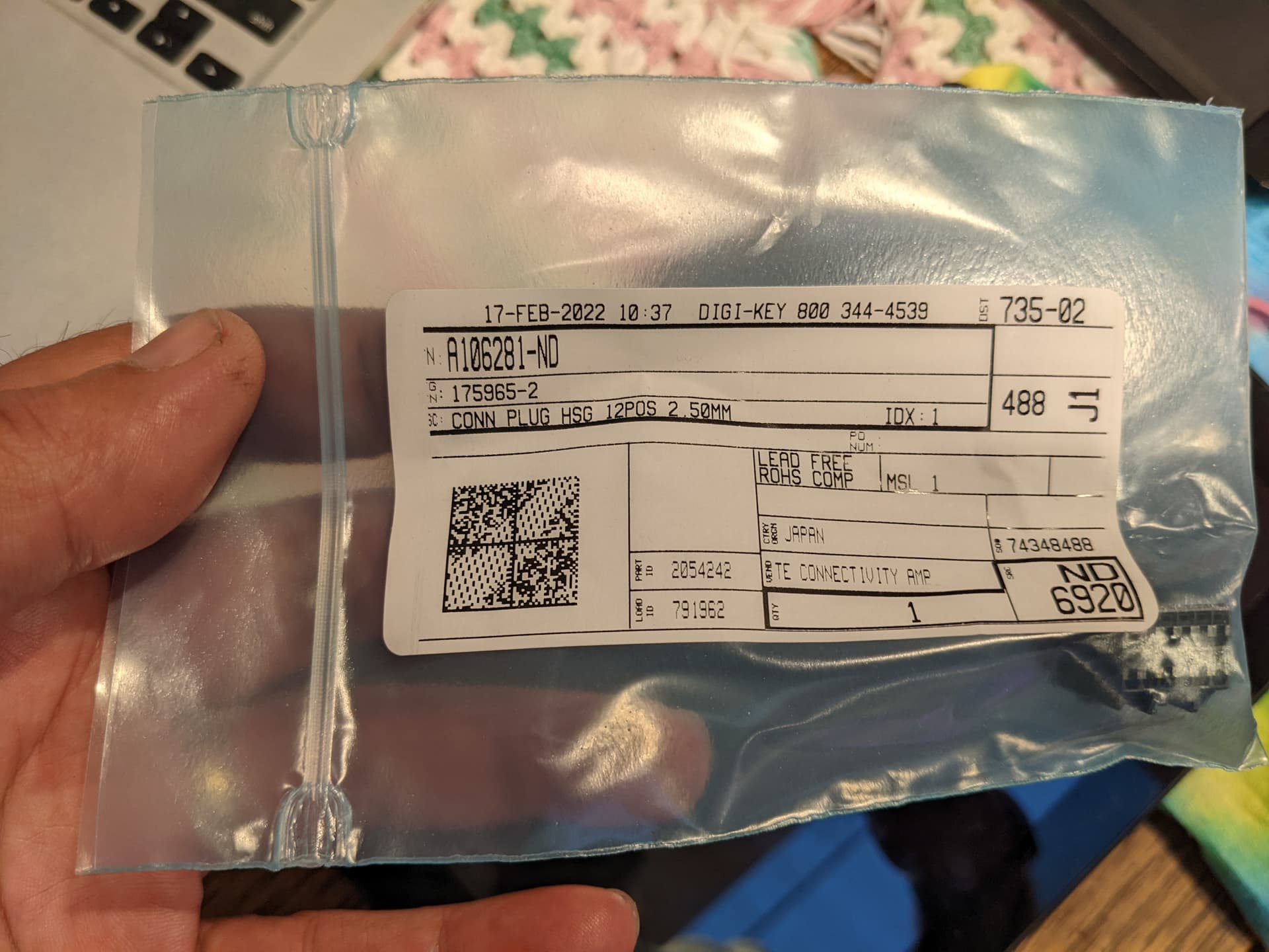
Next Mouser or Digikey order will include the 12 pin connector and I’ll move all the pins to it.
---
### Author:  [@dougl](https://community.electricforum.com/u/dougl)
#### Post date: [February 20, 2022, 1:32am UTC](https://community.electricforum.com/t/2002-doa-in-san-diego-after-pothole-hit/23450/85 "2022-02-20T01:32:35Z")
12 pin connector
---
### Author:  [@AssyRequired](https://community.electricforum.com/u/AssyRequired)
#### Post date: [February 20, 2022, 1:45am UTC](https://community.electricforum.com/t/2002-doa-in-san-diego-after-pothole-hit/23450/86 "2022-02-20T01:45:36Z")
Did any Pins come with?
---
### Author:  [@dougl](https://community.electricforum.com/u/dougl)
#### Post date: [February 20, 2022, 1:58am UTC](https://community.electricforum.com/t/2002-doa-in-san-diego-after-pothole-hit/23450/87 "2022-02-20T01:58:43Z")
nope, those have to be purchased separately and I didn’t.
I’ll be moving the 5 pins from the hacked up 8 pin connector to the 12 pin connector to have a more secure display harness.
---
### Author:  [@Inwo](https://community.electricforum.com/u/Inwo)
#### Post date: [February 20, 2022, 2:08am UTC](https://community.electricforum.com/t/2002-doa-in-san-diego-after-pothole-hit/23450/88 "2022-02-20T02:08:01Z")
A bear to repin. Took me forever to figure it out yesterday after building a harness
I have pins but that won’t help you .
---
### Author:  [@dougl](https://community.electricforum.com/u/dougl)
#### Post date: [February 20, 2022, 2:31am UTC](https://community.electricforum.com/t/2002-doa-in-san-diego-after-pothole-hit/23450/89 "2022-02-20T02:31:38Z")
I fought getting pin 5 out for about an hour and eventually cut up the connector. That’s when I learned the locking pin is in the larger holes and not the small holes. I ended up having to also cut off the end of the hacked 8 pin connector to get it to work with pin 5 moved next to pin 4. Getting pin 4 out was much easier knowing where the locking clip is. And also knowing you don’t need to preserve the connector housing.
[Previous page](https://community.electricforum.com/t/2002-doa-in-san-diego-after-pothole-hit/23450.md?page=4)